Chapter 6 Function Introduction
Shenzhen Hpmont Technology Co., Ltd.
- 84 -
HD3N Series User Manual V1.1
Ref. code
Function Description
Setting Range [Default]
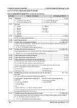
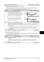
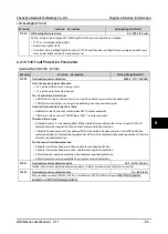
6: Process PID regulating upper limit.
•
F04.11 = 1 (analogue sets upper limit of PID regulator), process PID regulating upper limit is set by
corresponding input voltage.
7: Process PID regulating lower limit.
•
F04.12 = 1, process PID regulating lower limit is set by corresponding input voltage.
9: Electric torque limit when motor is forward.
•
F10.09 units = 1, electric torque limit when motor forwards is set by corresponding input voltage.
10: Electric torque limit when motor is reverse.
•
F10.09 tens = 1, electric torque limit when motor reverses is set by corresponding input voltage.
11: Re-generative torque when motor is forward.
•
F10.10 tens = 1, re-generative torque when motor forwards is set by corresponding input voltage.
12:Re-generative torque when motor is reverse.
•
F10.10 units = 1, re-generative torque when motor is reverse is set by corresponding input voltage.
13: Torque command setting.
•
F21.00 = 1, setting command is set by corresponding input voltage.
15: Upper limit frequency in torque control.
•
F21.04 = 2, speed limit is set by corresponding input voltage.
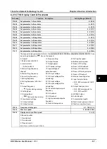
F16.05
AI1 bias
-100.0 - 100.0 [0.0%]
F16.08
AI2 bias
F16.06
AI1 gain
0.00 - 10.00 [1.00]
F16.09
AI2 gain
F16.07
AI1 filtering time
0.01 - 10.00 [0.05s]
F16.10
AI2 filtering time
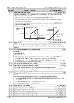
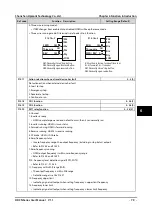
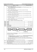
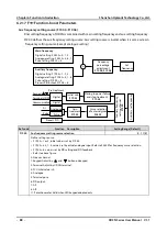
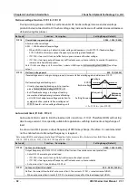
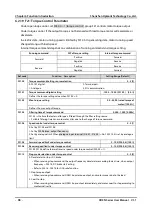
When AI1 - AI2 is open loop frequency setting source, the relationship between the analogue input and the
analogue value after calculating is shown as figure:
Analogue actual value is calculated by filter, bias and gain. Group F05 calculates the analogue value and
gets the internal analogue setting of HD3N.
•
The formula is:Y = kX+bA
•
Y is analogue after calculating, X is value before adjusting, k is analogue input gain (F16.06 and F16.09),
b is analogue input bias (F16.05 and F16.08), A is analogue max input (10V or 20mA).
•
F16.07 and F16.10 define the channel filter time and filters the input signal. The longer filter time, the
stronger immunity ability but the shorter respond time; the shorter filter time, the shorter respond time
but the weaker immunity ability.
•
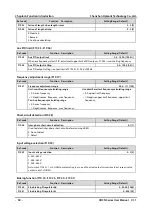
When AI2 selects current input, short-connect pin 2&3 on control board.
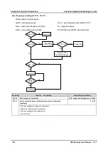
F16.17
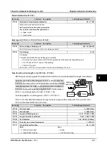
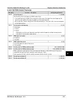
Max. input pulse frequency
0 - 10000 [10000Hz]
When set the DI6 as pulse input, F16.17 defines the max. input pulse frequency.
F16.18
Input pulse filter time
0.01 - 10.00 [0.20s]
It is used to filter the input pulse frequency and filter out the small fluctuations in the pulse frequency.
Analogue
actual value
Analogue
input filtering
Analogue input gain
Analogue input bias
Analogue value
after calculating
AI display value
AI display value
(after calculating)

