Appendix A Parameters
Shenzhen Hpmont Technology Co., Ltd.
- 128 -
HD3N Series User Manual V1.1
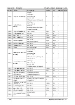
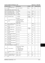
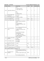
Ref. Code
Function
Setting Range
Default
Unit
Attribute Setting
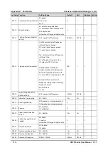
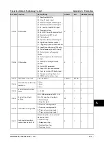
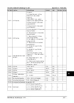
F15.18
DO1 function
0: Unused
1: Inverter is ready
2: Inverter running
3: Forward running
4: Reverse running
5: DC brake
6: Zero-frequency status
7: Zero-frequency running
9,10: Frequency level detection
signal (FDT1,FDT2)
11: Frequency within FAR range (FAR)
12: Frequency upper limit
13: Frequency lower limit
14: Upper/Lower limit of wobble
15: Running in simple PLC mode
16: Pause simple PLC running
17: Simple PLC loop done
18: Simple PLC phase running is
finished
19: Simple PLC running is finished
20: Signal output from SCI
21: Set fully met running time
22: Timing function
23: Set fully counting value
24: Specific fully counting value
2525: Set length
2727: Analogue input exceeding
limit
29:Stop in under-voltage condition
30: Overload detection signal
31: Inverter fault
32: External fault
33: Fault of inverter is reset
automatically
35: Dormancy function
36: System is running
38: High speed pulse output (DO2
only)
2
1
○
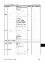
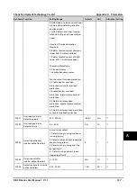
F15.19
DO2 function
0
1
○
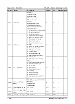
F15.20
RLY1 relay function
31
1
○
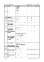
F15.24
Terminal output logic
setting
Bit0 - Bit1 corresponds to DO1 - DO2
Bit2 = RLY1
0: Positive logic
1: Negative logic
0
1
○
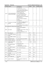
F15.25
Delay time at ON side for
timing
0.00 - 300.00s
0.00s
0.01s
○
F15.26
Delay time at OFF side for
timing
0.00 - 300.00s
0.00s
0.01s
○
F15.27
Speed within FAR range
0.00 - 100.00Hz
2.50Hz
0.01Hz
○

