Shenzhen Hpmont Technology Co., Ltd.
Chapter 4 Electrical Installation
HD3N Series User Manual V1.1
- 17 -
Chapter 4
Electrical Installation
4.1
Precautions
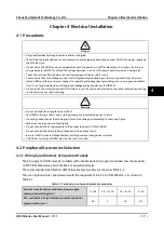
•
Only qualified electrical engineer can perform wiring job.
•
To facilitate the input side over-current protection and outage maintenance, connect HD3N with power supply via
the MCCB or fuse.
•
Do not dismantle HD3N or do wiring operation until the power is cut-off for more than 10 minutes, the internal
charge indicator of HD3N is off and the voltage between (+) and (-) of the main circuit terminals is below 36V.
•
Check the wiring carefully before connecting emergency stop or safety circuit.
•
There is more than 3mA leakage current in HD3N grounding, depending on the running conditions. To ensure
safety, HD3N and the motor must connect to separate and independent grounding wire, so as to ground reliably.
It must use Type B mode when utilize ground leakage protection devices (ELCB/RCD).
•
Do not touch the wire terminals of HD3N when it is live. The main circuit terminals are neither allowed connecting
to the enclosure nor short-circuiting.
•
Do not do dielectric strength test on HD3N.
•
For HD3N with more than 2 year’s storage, please use regulator to power it slowly.
•
Do wiring connection of the braking resistor or the braking unit according to the wiring figure.
•
Make sure the terminals are fixed tightly.
•
Do not connect the AC supply cable to the output terminals U/V/W of HD3N.
•
Do not connect the phase-shifting capacitors to the output circuit.
•
Be sure HD3N has ceased output before switching motor or change-over switches.
•
The DC bus terminals of HD3N must not be short-circuited.
4.2
Peripheral Accessories Selection
4.2.1
Wiring Specifications of Input and Output
The AC supply to HD3N must be installed with suitable protection against overload and short-circuits,
i.e. MCCB (molded case circuit breaker) or equivalent device.
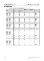
The recommended specification of MCCB, contactor & cables are shown as Table 4-2.
The size of ground wire should accord with the requirement in 4.3.5.4 of IEC61800-5-1, as shown in
Table 4-1.
Table 4-1 Sectional area of ground protective conductor
Sectional area S of phase conductor (power supply
cable) while installing (mm
2
)
S ≤ 2.5
2.5 < S ≤ 16
16 < S ≤ 35
S > 35
Min. sectional area Sp of relative protective conductor
(ground cable) (mm
2
)
2.5
S
16
S/2
Danger
Warning
4

