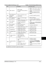
Chapter 6 Function Introduction
Shenzhen Hpmont Technology Co., Ltd.
- 88 -
HD3N Series User Manual V1.1
6.2.17
F19: Function-boost Parameters
Aux frequency setting source (F19.00 - F19.06)
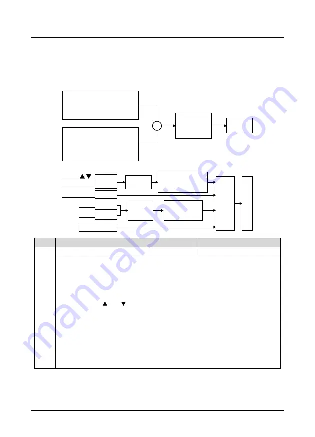
Final setting frequency of HD3N is combined with main setting frequency and aux setting frequency.
F19.00 defines the aux frequency setting source. Aux setting source is invalid when it is same as main
frequency setting source (except analogue setting).
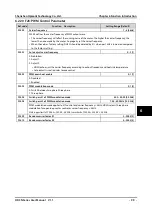
Ref. code
Function Description
Setting Range [Default]
F19.00
Aux frequency setting source selection
0 - 11 [0]
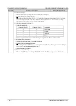
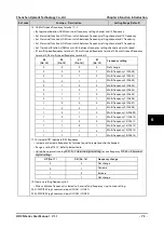
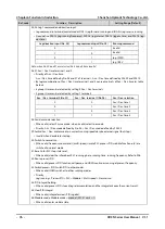
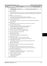
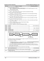
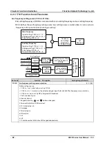
Define setting source.
•
F19.00 = 1 or 2, initial value is set by F19.03.
•
F19.00 = 4,5,7 - 8, value is set by actual analogue input. Refer to F05.00 for frequency curve selection.
•
F19.00 = 6, value is set by PID setting and PID feedback.
•
Refer to above figure.
0: No aux channel.
1: Keypad. Adjust by
and
button on keypad.
2: Terminal. Adjust by UP/DN terminal.
3: SCI. Initial value is 0.
4: Analogue.
5: Terminal puse.
6: PID output.
7: AI1.
8: AI2.
11: Potentionmeter. Valid when LED keypad adopted only.
±
Main frequency:
Digital setting F00.10 = 0, 1, 2
Analogue setting F00.10 = 3, 6, 7
Pulse setting F00.10 = 4
Auxiliary frequency:
Digital setting F19.00 = 1, 2, 3
Analogue setting F19.00 = 4, 7, 8
Pulse setting F19.00 = 5
Process PID output F19.00 = 6
Frequency
percentage
adjustment
F19.05, F19.06
Initial value
F19.03
Storing in power failure
and stop treatment
F19.04
A
u
xil
ia
ry
fr
e
q
u
e
ncy
se
tt
ing
cha
nne
l
F
19.
00
A
u
xil
ia
ry
s
e
t f
re
q
u
e
ncy
Curve selection
of external given
F05.00
Gain
treatment
F19.02
Set
frequency
Keypad
Pre-treatment
Digital
Digital
Analogue
Pulse
Terminal UP/DN
Process PID
Communicaiton
AI
Pulse

