Shenzhen Hpmont Technology Co., Ltd.
Appendix A Parameters
HD3N Series User Manual V1.1
- 127 -
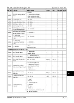
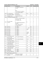
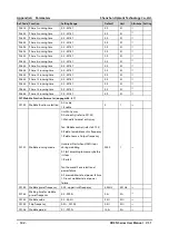
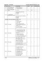
Ref. Code
Function
Setting Range
Default
Unit
Attribute Setting
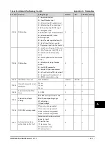
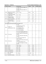
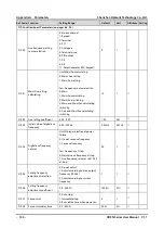
F15.04
DI5 function
37: Reset wobble state
38: Stop DC brake input
39: External stop NO contact input
40: External stop NC contact input
41,42: Coast to stop NO/NC input
43: Emergency stop
44,45: NO/NC input for external fault
46: External reset (RST) input
48: Timing input
49: Input for clearing actual length
50: Signal input to clear counter
51: Triggering signal input of counter
52: Length counting input (DI6 only)
53: Pulse frequency input (DI6 only)
54: Switch main/aux frequency
source
56: Switch speed control and torque
control
57: Polarity switching of torque
control
59: Switch PID parameter
85: Simple PLC pause command.
86: Activate terminal DC brake input
87: Frequency setting channel = 4
88: DWELL end enable in stop
0
1
×
F15.05
DI6 function
0
1
×
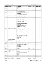
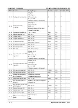
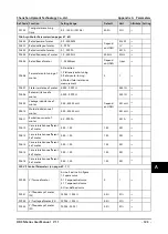
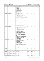
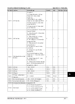
F15.12
UP/DN Acc. / Dec. rate
0.00 - 99.99Hz/s
1.00Hz/s
0.01Hz/s
×
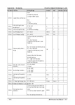
F15.13
Interval between terminal
detection
0: 2ms
1: 4ms
2: 8ms
0
1
○
F15.14
Terminal detection filter
times
0 - 10000
2
1
○
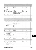
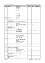
F15.15
Terminal input logic
setting
Bit0 - Bit8 correspond to DI1 - DI6
Bitx: DIy onput pos/neg logic
0: Positive logic
1: Negative logic
00
1
○
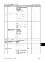
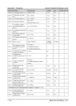
F15.16
FWD / REV running mode
0: Two-wire running mode 1
1: Two-wire running mode 2
2: Three-wire running mode 1
3: Three-wire running mode 2
0
1
×
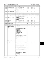
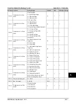
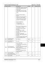
F15.17
Action selection when
extrenal device has fault
Protection action when external
device has fault
0: Coast to stop
1: Emergency stop
2: Decelerate to stop
3: Continue to run
0
1
×
A

