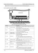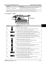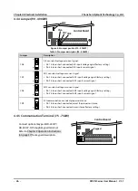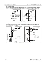
Shenzhen Hpmont Technology Co., Ltd.
Chapter 4 Electrical Installation
HD3N Series User Manual V1.1
- 19 -
4.2.2
Power Terminal Lug
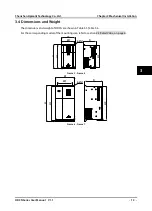
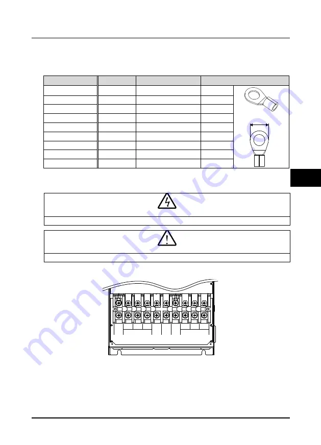
Select the lug of power terminal according to the size of terminal, screw size and max. outer diameter
of lug. Refer to Table 4-3. Take the TNR terminal as an example.
Table 4-3 Selection of power terminal lug
Size
Screw size
Tightening torque (N. M)
Max. outer diameter d (mm)
Frame 3
M4
1.2 - 1.5
10.2
Frame 4
M5
2.3 - 2.5
12.3
Frame 5 / 6
M6
4.0 - 5.0
17.0
Frame 7
M8
9.0 - 10.0
20
Frame 8
M10
17.6 - 22.5
30
Frame 9
M12
31.4 - 39.2
37
Frame 10
M12
31.4 - 39.2
40
Frame 11
M12
31.4 - 39.2
40
Frame 12
M16
48.6 - 59.4
40
4.3
Main Circuit Terminals and Wiring
•
The bare portions of the power cables must be bound with insulation tapes.
•
Ensure that AC supply voltage is the same as rated input voltage of HD3N.
4.3.1
Supply and Motor Terminal
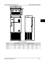
Frame 3 - Frame 7 supply and motor terminal
d
Danger
Warning
L1 L2 L3
W
V
U
PE
(+) (-) BR
POWER
MOTOR
4

