99
Open Correction
5.2 Open Correction
With open correction, it is possible to reduce the influence of the floating impedance of the mea
-
surement cables and thereby to enhance the accuracy of measurement. It is effective for measure
-
ment samples whose impedance is relatively high.
There are the following three methods for setting the open correction.
All correction
•
The correction values are obtained for all measurement frequencies (p. 100).
•
The range of measurement frequencies to correct can be set.
See "Correction range limitation function (to shorten the correction time)" (p. 101).
Spot correction
The correction values are obtained at the set measurement frequency only (p. 103).
Off
Open correction data becomes invalid (p. 111).
Before performing open correction
1
Review the information shown under "Check the following before performing correction:"
2
Follow the instructions in "5.1 Setting the Cable Length (Cable Length Correction)" (p. 98).
3
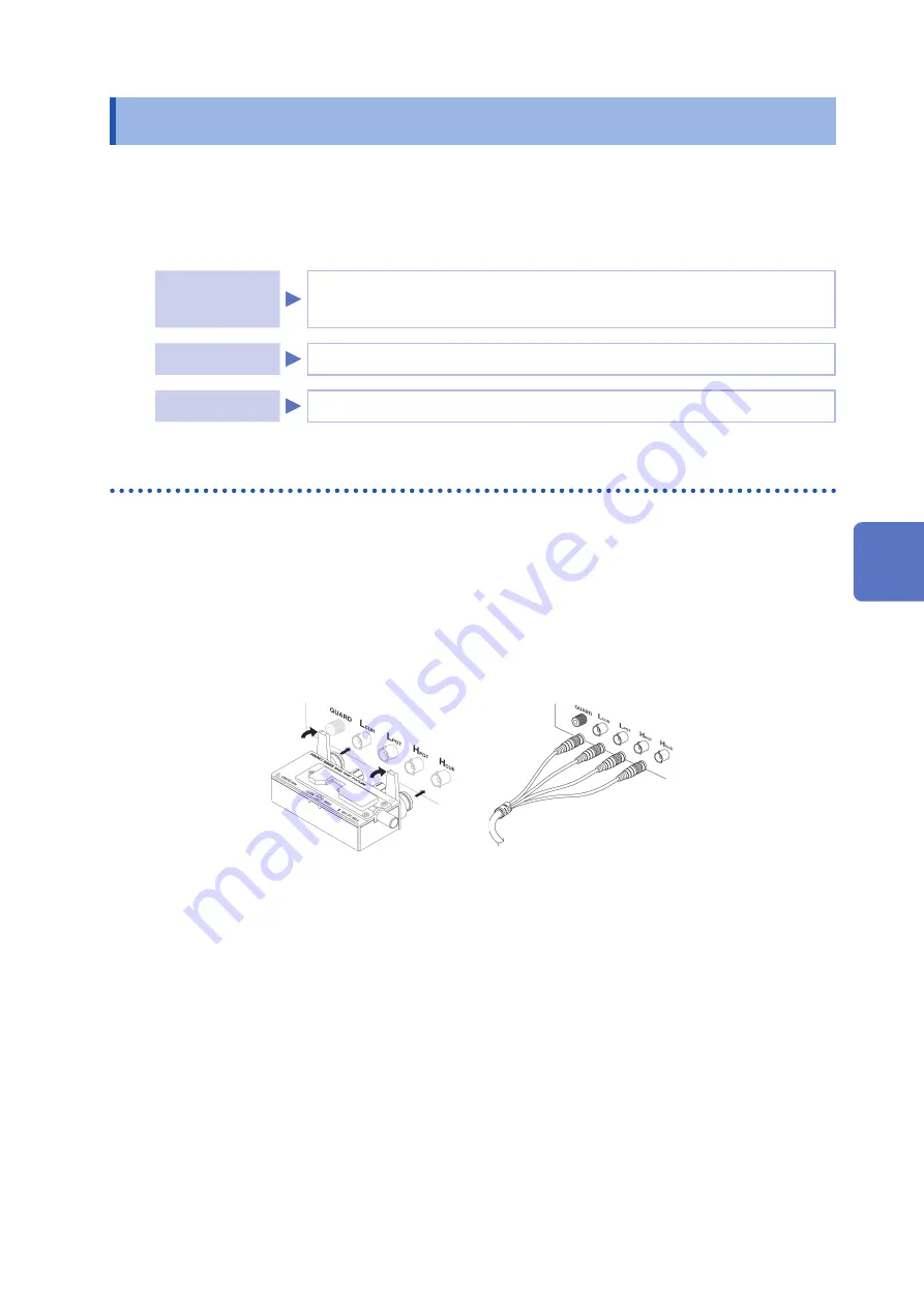
Arrange the measurement cables, probes, and fixtures as they will be when measurement
will actually be performed.
Changing the configuration of them may result in correction not being performed properly.
For more information about how to connect the instrument, see "2.4 Connecting the Measurement
Cables, Probes, or Fixture" (p. 35).
4
Adjust the distance between the HI and LO terminals of the measurement cable or Hioki op-
tional probe or fixture to the width of the measurement sample and place them in the open
state
*
.
(What constitutes the open state varies with the measurement cable, probe, or fixture being used
[p. 2 to p. 5]. For more information, review the appropriate user manual.)
*: Defined as when the H
CUR
terminal and H
POT
terminal, as well as the L
CUR
terminal and the L
POT
terminal, are connected while the HIGH terminal and LOW terminal are not connected.
5
Perform guarding.
(See "Appx. 2 Measurement of High Impedance Components" (p. Appx.3).)
Perform open correction after completing the above procedure.
See "All correction" (p. 100), and "Spot correction" (p. 103).
5
Error Correction
Содержание IM3536
Страница 20: ...16 Operating Precautions ...
Страница 34: ...30 Screen Layout and Operation ...
Страница 140: ...136 Testing the System Self diagnosis ...
Страница 224: ...220 About Measurement Times and Measurement Speed ...
Страница 240: ...236 Discarding the Instrument ...
Страница 254: ...Appx 14 Dimensional Diagram Appx 10 Dimensional Diagram 230 114 15 48 33 33 25 35 119 1 330 1 Unit mm ...
Страница 264: ...Appx 24 Device Compliance Statement ...
Страница 270: ...Test Equipment Depot 800 517 8431 99 Washington Street Melrose MA 02176 TestEquipmentDepot com ...


