Appx.
4
Measurement of In-circuit Components
Appx. 3 Measurement of In-circuit Components
Measure an in-circuit component after providing
guarding.
4
3
2
4
3
2
R
R
R
R
R
R
R
+
+
+
•
=
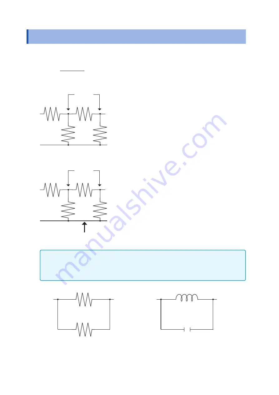
Referring to the following figure, when measuring a resistance
value for the resistor
R
2
, even if the tips of the two probes are
contacted against the ends of the resistor
R
2
, considering the
sum of the current flowing through the resistor
R
2
and the cur-
rent flowing through the resistors
R
3
and
R
4
what is obtained is
the resistance value for the parallel combination:
R
1
R
2
R
3
R
4
H
L
If as shown in the next figure a guard terminal is used, the cur
-
rent flowing through the resistors
R
3
(not flowing through
R
4
) is
absorbed by this guard terminal, so that the resistance value
for the resistor
R
2
is accurately measured.
R
1
R
2
R
3
R
4
H
L
Guard terminal
•
The accuracy of measurement will not be improved in cases where for example
R
2
>>
R
3
and
R
3
is close to
zero.
•
As shown in the figure below, it is not possible to use this type of separation process for testing of the im
-
pedance values of two resistors or other elements of identical types which are connected in parallel, or for
testing of the impedance values of a coil and a capacitor which are connected in parallel.
Two resistors in parallel
Coil and capacitor in parallel
Содержание IM3536
Страница 20: ...16 Operating Precautions ...
Страница 34: ...30 Screen Layout and Operation ...
Страница 140: ...136 Testing the System Self diagnosis ...
Страница 224: ...220 About Measurement Times and Measurement Speed ...
Страница 240: ...236 Discarding the Instrument ...
Страница 254: ...Appx 14 Dimensional Diagram Appx 10 Dimensional Diagram 230 114 15 48 33 33 25 35 119 1 330 1 Unit mm ...
Страница 264: ...Appx 24 Device Compliance Statement ...
Страница 270: ...Test Equipment Depot 800 517 8431 99 Washington Street Melrose MA 02176 TestEquipmentDepot com ...


