Channel mapping
The function of each channel is determined by the
transmitter and not the receiver. The channel map-
ping can be changed directly in the receiver program-
ming the "
Telemetry
" menu and indirectly through the
menu point "
Transmitter output
" of the base menu.
Installing the receiver
Whatever
Graupner
receiver system you use, the
procedure is the same
.
For aircraft models, the receiver is installed behind
a strong bulkhead or it is protected against dust and
splash water in car and ship models. When you install
the receiver, make sure that it is not excessively air-
tight to prevent it from overheating during operation.
The receiver may not directly touch the fuselage or
chassis since they can directly transmit motor vibra-
tion or impact from landing. When installing the re-
ceiver in a model with a gas motor, all of the parts
must be protected to prevent exhaust or oil from pen-
etrating. This holds true in particular for the ON/OFF
switch that is installed in the shell of the model in most
cases.
Install the receiver so that the connecting cables for
the servos and power supply remain loose, and so
that the receiving antennas are at least 5 cm from all
large metal parts or wires that do not directly originate
from the receiver. This includes carbon fiber parts,
servos, electric motors, fuel pumps, all types of ca-
bles, etc. in addition to steel parts.
It is preferable to install the receiver away from all oth-
er installed parts at an easily accessible location in
the model. Servo cables may not be wound around
antennas or run next to them.
Note that the cables can shift under the influence of
acceleration during flight. You therefore need to make
sure that the cables cannot move to be directly ad-
jacent to antennas. Moving cables can interfere with
reception.
Installing the receiver
Installing the receiver antennas
In case of single antenna, the orientation is not crucial.
In the case of diversity antennas (two antennas), the
active end of the second antenna should be at a 90°
angle from the end of the first antenna, and the dis-
tance between the active ends should ideally be more
than 125 mm.
If the fuselages are made of carbon fiber, the ends
of the antennas should extend from the fuselage by
at least 35 mm. If necessary, exchange the approx.
145 mm standard antennas for HoTT receivers with
the 300 mm or 450 mm long antennas No.
33500.2
or
33500.3
.
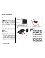
Servo connections and polarity
The servo connections of the
Graupner
-HoTT receiv-
er are numbered. The supply voltage runs through all
the numbered connections. The polarity of the plug-in
system cannot be reversed. When inserting the plug,
note the small bevels on the side. Do not apply force.
Attention
Do not reverse the polarity of these connections!
This can destroy the receiver and connected de-
vices.
Notice
In compact receivers like the GR-12L HoTT the
outputs 1 … 6 are reverse of 180° if compared to
bigger receivers, for this reason we recommend
to pay a very lot of attention while you connect any plug
to the receiver. If applicable, use a V or Y cable (No.
3936.11
).
15
Installing the receiver
Содержание mz-24 PRO
Страница 13: ...13 Personal notes...
Страница 19: ...19 Personal notes...
Страница 37: ...37 Personal notes...
Страница 59: ...Touch 59 Base menu Model selection...
Страница 79: ...79 Personal notes...
Страница 89: ...89 Personal notes...
Страница 115: ...115 Personal notes...
Страница 153: ...Helicopter model function menus Common function menus 153 Personal notes...
Страница 169: ...169 Personal notes...
Страница 187: ...187 Personal notes...
Страница 199: ...199 Personal notes...
Страница 207: ...Fixed wing model function menus System menus 207 Personal notes...
Страница 211: ...211 Personal notes...
Страница 219: ...219 Personal notes...
Страница 237: ...237 Personal notes...
Страница 238: ...238 Personal notes...
Страница 239: ...239 Personal notes...


