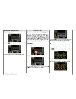
Use the same procedure for the other settings.
Notices
• The controllers assigned in this sub-menu
globally affect all the phases. Only the offset in
the second line and the "travel setting" in the
third and fourth column affect specific phases.
• If, with a model that has flaps, you assign to
input 6 a control or switch identified as
"FLAP(1L)", its function is dependent on the
current setting in the line "
ACT
" of the sub-
menu "
Flap Sett
" of the function menu (page
). If the value field to the right of "
ACT
" is
INH
or
OFF
, then this control or switch acts ex-
clusively on servo 6 and possibly 7 with the
values set in the sub-menu "D/R,Exp". Other-
wise, this control or switch assumes the func-
tion of Q.Link trimming with the value set in
the sub-menu "
Flap Sett
".
Phase depending settings
In contrast to the previously described - phase influ-
encing - control and switch assignation in the "CTL
Set" column the values act in the following described
columns "OFFSET" and "-" so as the phase
specific "symmetrical delay" which are available in a
specific page. Recognizable on the top left side of the
display in green color is displayed the phase name. As
standard is displayed the name of the phase 1, which
is indicated by the name "NORMAL" or "PHASE 1".
As soon as you will have defined one or many oth-
er phases in the "
PHASE
" menu, you will be able to
switch among those phases. Activate the correspond-
ing switch or switches if desired to switch between
the phases.
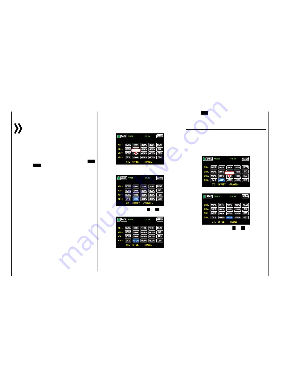
"OFFSET" column
Change the center of each control element, i.e., its
zero point (if desired with reference to a specific
phase), in this column.
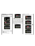
Touch the offset value to be changed, for example:
Touch
The color of the value field switches from black to
blue:
Set the desired value with the
+
or
–
button at the
right edge, for example:
The adjustment range is ±125%.
Touch the
RES
button to reset a changed value in the
blue (and hence active) field to the default value.
Use the same procedure for the other settings.
"- " column
In this column is set the travel of each control ele-
ment, specifically for each page.
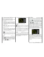
Touch the left value field in the corresponding line to
set a value to the minus side of the control travel, and/
or on the right to set a value on the plus side of the
control travel, for example:
Touch
The color of the field switches from black to blue:
Set the desired value with the
+
or
–
button at the
right edge.
The adjustment range is ±125%.
Use the same procedure for a value on the plus side
of the control travel, for example:
92
Base menu - Control/switch setting
Содержание mz-24 PRO
Страница 13: ...13 Personal notes...
Страница 19: ...19 Personal notes...
Страница 37: ...37 Personal notes...
Страница 59: ...Touch 59 Base menu Model selection...
Страница 79: ...79 Personal notes...
Страница 89: ...89 Personal notes...
Страница 115: ...115 Personal notes...
Страница 153: ...Helicopter model function menus Common function menus 153 Personal notes...
Страница 169: ...169 Personal notes...
Страница 187: ...187 Personal notes...
Страница 199: ...199 Personal notes...
Страница 207: ...Fixed wing model function menus System menus 207 Personal notes...
Страница 211: ...211 Personal notes...
Страница 219: ...219 Personal notes...
Страница 237: ...237 Personal notes...
Страница 238: ...238 Personal notes...
Страница 239: ...239 Personal notes...


