To safely operate the model, a reliable power supply
is required. If the receiver voltage shown on the trans-
mitter display always drops or is generally (too) low
even though the linkage moves freely, the battery is
full, the cross-section of the battery connecting cable
is sufficient, and the transition resistance at the plug-
in connections is minimal, etc., observe following:
First make sure that the battery remains fully charged
when initially operating the model. Make sure that the
resistance of the contacts and switches is low. Mea-
sure the voltage drop over the installed switch cables
under a load since even robust, new switches cause
a voltage drop of up to 0.2 V. This value can be sev-
eral times higher due to aging and oxidation of the
contacts. In addition, constant vibration and shaking
of the contacts also gradually increase the transition
resistance.
Furthermore, even small servos such as a
Graupner/
JR
DS-281 draw stall current to 0.75 A when you stop
under a load. Four of these servos in a foam airplane
can hence draw up to 3 A from the on-board power
supply.
Furthermore, servos connected to a 2.4 GHz receiver
receive control pulses more frequently than compara-
ble receivers in the classic frequency range. This af-
fects the power consumption of the receiver system
as well as the characteristic of many modern digital
servos of maintaining the last position specified by
the last control pulse until the next pulse arrives.
You should not only therefore choose a power supply
that does not fail under a permanent high load and
always provides sufficient voltage. To calculate the re-
quired battery capacity, add at least 350 mAh for each
analog servo, and at least 500 mAh for each digital
servo.
Using this method, a battery with 1400 mAh rep-
resents the absolute minimum for supplying power to
a receiver with four analogue servos. In your calcula-
tion, also include the receiver which requires about
70 mA due to its bidirectional function.
Apart from the above considerations, it is generally
recommendable to connect the receiver to the power
supply using two cables. As usual, connect cable "1"
to the "6+B" or "12+B-" output of a GR-16 or GR-
24 receiver, and cable "2" to the opposite end of the
connector strip labeled "1+B-" or "11+B-" of the re-
ceiver. When, for example, using a switch or voltage
regulator with two power supply cables leading to the
receiver. Between the cable and receiver, you can use
a V or Y cable (No.
3936.11
, see figure) if one or both
receiver connections also need to be connected to a
servo, speed controller, etc. With the double connec-
tion to the switch or voltage controller, you not only
reduce the risk of a cable rupture but also ensure an
even power supply to the connected servos.
If you connect a separate battery to each battery
connection, be sure that each of the batteries have
the same rated voltage and capacity. Never connect
different battery types or batteries with strongly dif-
ferent charges since this can cause an effect similar
to a short circuit. In such cases for safety reasons,
insert voltage stabilizing elements such as the PRX-
5A receiver power supplies between the batteries and
receiver:
For safety reasons, never used battery boxes or dry
batteries.
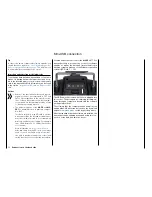
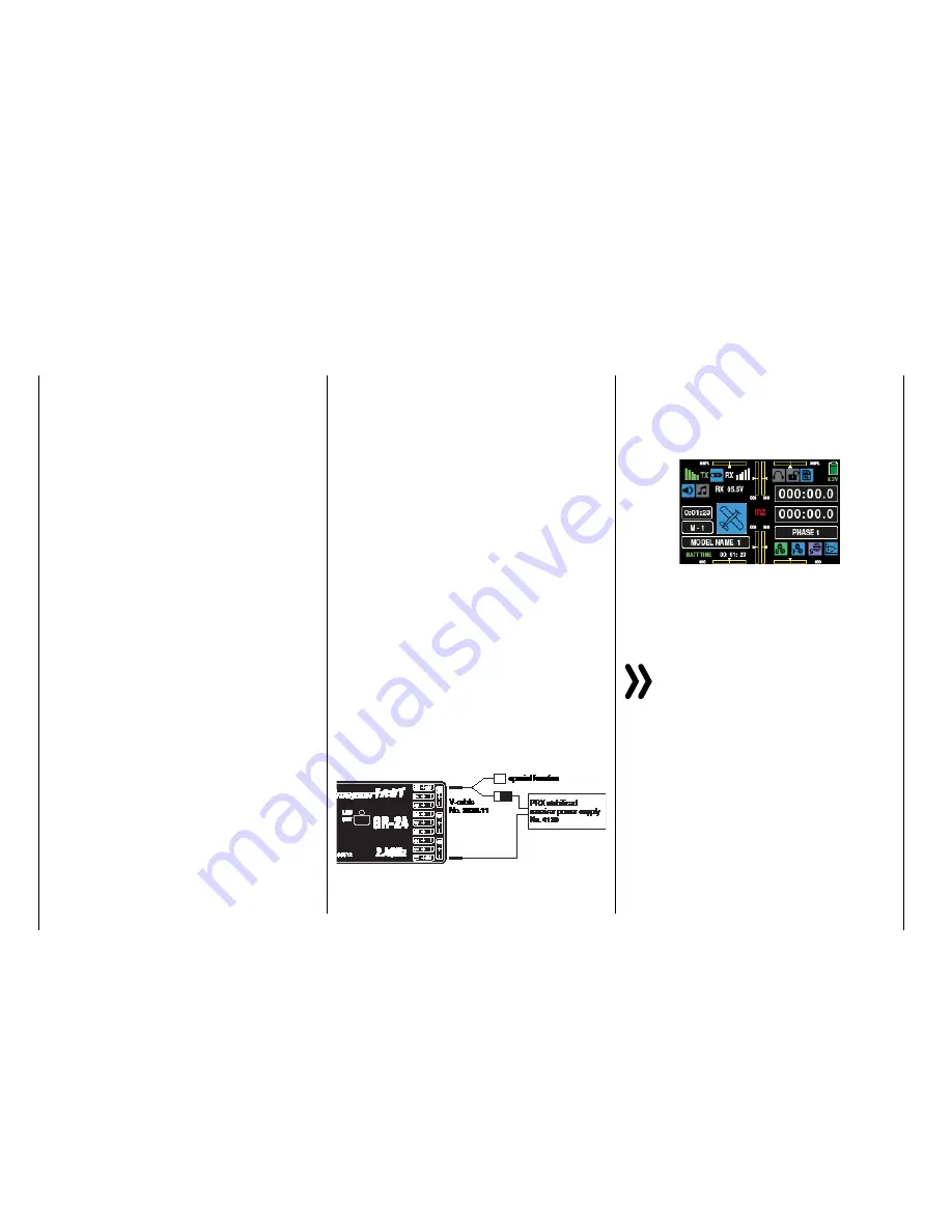
The voltage of the on-board power supply is graph-
ically represented, when the model is in use, in the
upper right side of the display so as underneath in
green numerically:
If the voltage falls below the warning threshold (nor-
mally 3.8 V) which can be adjusted in the "
RX SERVO
TEST
" display of the "SETTING & DATA VIEW" of the
"
Telemetry
" menu, a visual and acoustic low-voltage
warnings are generated.
Attention
The battery level should be checked regularly. Do
not wait to charge the battery until the voltage
decreases enough for a warning signal to be
generated.
Tip
A summary of the batteries, chargers and measuring
devices for checking the power sources can be found
in the main
Graupner
FS catalogue as well as on the
Internet at
www.graupner.de
.
20
Installation notice - Receiver system power supply
Receiver system power supply
Содержание mz-24 PRO
Страница 13: ...13 Personal notes...
Страница 19: ...19 Personal notes...
Страница 37: ...37 Personal notes...
Страница 59: ...Touch 59 Base menu Model selection...
Страница 79: ...79 Personal notes...
Страница 89: ...89 Personal notes...
Страница 115: ...115 Personal notes...
Страница 153: ...Helicopter model function menus Common function menus 153 Personal notes...
Страница 169: ...169 Personal notes...
Страница 187: ...187 Personal notes...
Страница 199: ...199 Personal notes...
Страница 207: ...Fixed wing model function menus System menus 207 Personal notes...
Страница 211: ...211 Personal notes...
Страница 219: ...219 Personal notes...
Страница 237: ...237 Personal notes...
Страница 238: ...238 Personal notes...
Страница 239: ...239 Personal notes...


