G900X/G950 Installation and Maintenance Manual – 3
rd
Party Interfaces
Page 14-3
190-00719-00
Revision D
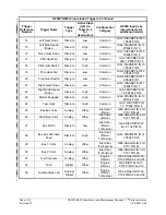
G900X/G950 Annunciation Triggers, Continued
Trigger
Reference
Number
Trigger Name
Trigger
Type
Active State
(refer to
Table 14-2
for
description)
Configuration
Category
G900X Input (see
interconnects for
additional details)
34
Fuel Quantity Right
Analog/
Digital
Other
Engine
(Piston/
Turboprop)
GEA ANALOG IN 3A,
P702 PINS 56 and 57
35
Oil Pressure
Analog
Other
Engine
(Piston/
Turboprop)
GEA ANALOG IN 2,
P701 PINS 24 and 25
36
Chip Detect
Discrete
Low
Engine
(Turboprop)
GIA2 DISCRETE IN* 4,
2P604 PIN 12
37
Ng
Digital
Other
Engine
(Turboprop)
GEA DIGITAL IN* 1,
P701 PINS 2 and 11
38
Np
Digital
Other
Engine
(Turboprop)
GEA DIGITAL IN* 2,
P701 PINS 3 and 12
39
Torque
Analog
Other
Engine
(Turboprop)
GEA ANALOG IN 3,
P701 PINS 42 and 43
Table 14-2. Active State Descriptions
Active State
Description
Active High Discretes
This input type should be wired to the appropriate positive circuit such that it
senses the reference voltage only when the trigger should be active. Active
when sensing 10 <= Vin <= 33VDC with >=75 uA source current (see
below). There are no active high discretes on the GEA.
DISCRETE IN pins:
INACTIVE: Vin
≤
3.5VDC
ACTIVE: 10
≤
Vin
≤
33VDC with
≥
75 uA source current
Source current is internally limited to 1.5 mA max for a 10-33VDC input
See Appendix F-J for details on active versus inactive states.
Active Low Discretes
Active when the input senses ground (via failure output or discrete
microswitch wired to ground). See Appendix F-J for details on active versus
inactive states.
Analog/Digital
Should be wired to an analog or digital input according to the G900X/G950
Appendix F-J.
Other
Activation of analog triggers may vary depending on airframe, engine, and
electrical specific annunciation logic. See Tables 14-4 and 14-7 for details.


