


G900X/G950 Installation and Maintenance Manual – Pinouts
Page A-15
190-00719-00
Revision D
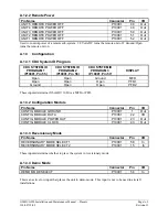
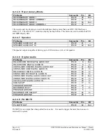
A.2.4.2 Lighting Bus
Pin Name
Connector
Pin
I/O
14 V LIGHTING HI
P3472
51
In
28 V LIGHTING HI
P3472
52
In
The GMA 1347 can be configured to track a 28 VDC or 14 VDC lighting bus using these inputs. The
GMA 1347 can also automatically adjust for ambient lighting conditions based on photocell input on the
PFD/MFD by digital means.
A.2.4.3 RS-232 Serial Input/Output
Pin Name
Connector
Pin
I/O
RS-232 OUT 1
P3472
6
Out
RS-232 IN 1
P3472
7
In
RS-232 OUT 2
P3472
38
Out
RS-232 IN 2
P3472
39
In
The RS-232 outputs conform to EIA/TIA-232C with an output voltage swing of at least ±5 V when
driving a standard RS-232 load.
A.2.4.4 Marker Beacon Functions
Pin Name
Connector
Pin
I/O
MIDDLE MARKER SENSE
P3472
34
Out
AIRWAY/INNER MARKER EXT LAMP OUT
P3472
74
Out
MIDDLE MARKER EXT LAMP OUT
P3472
75
Out
OUTER MARKER EXT LAMP OUT
P3472
76
Out
MARKER ANTENNA HI
P3472
78
In
MARKER ANTENNA LO
P3472
59
--
Marker Beacon connections are listed in the following table. The antenna input is connected to pins 78
(HI or Center Conductor) and 59 (LO or Shield).
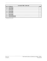
A.2.4.5 External Configuration Module
Pin Name
Connector
Pin
I/O
Configuration Module Ground
P3472
1
--
Configuration Module Power
P3472
21
In
Configuration Module Data
P3472
40
In/Out
Configuration Module Clock
P3472
60
In/Out
The configuration module contains an I2C temp sensor and EEPROM. The configuration module, if
required, is located in the connector backshell. Most installations will not require a configuration module
in the 1347 backshell, as the data will be stored with the GDU 1040.