Page A-42
G900X/G950 Installation and Maintenance Manual – Pinouts
Revision D
190-00719-00
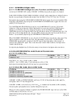
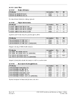
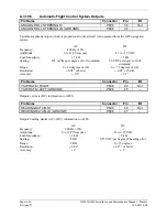
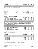
A.3.18 DME Interface and ADF Electrical Characteristics
A.3.18.1
Parallel DME Tuning
Pin Name
Connector
Pin
I/O
PARALLEL DME 1 MHZ-D
P602
33
Out
PARALLEL DME 100 KHZ-A
P602
37
Out
PARALLEL DME 100 KHZ-B
P602
39
Out
PARALLEL DME 100 KHZ-C
P602
40
Out
PARALLEL DME 100 KHZ-D
P602
42
Out
PARALLEL DME 50 KHZ
P602
43
Out
PARALLEL DME 1 MHZ-A
P602
45
Out
PARALLEL DME 1 MHZ-B
P602
46
Out
PARALLEL DME 1 MHZ-C
P602
47
Out
PARALLEL DME 100KHZ-E
P602
54
Out
PARALLEL DME 1MHZ-E
P602
56
Out
NAV DME COMMON
P602
41
In
For each of the parallel DME tuning discrete outputs:
INACTIVE: Floating (can be pulled up to externally sourced Vout in the range 0
≤
Vout
≤
33VDC)
Leakage current in the INACTIVE state is typically
≤
10 uA to ground
ACTIVE: Vout
≤
0.5VDC with
≤
20 mA sink current
Sink current must be externally limited to 20 mA max
NAV DME COMMON must be pulled low to indicate to the NAV module that it is the device channeling
the DME.
INACTIVE: 10
≤
Vin
≤
33VDC or Rin
≥
100k
Ω
ACTIVE: Vin
≤
1.9VDC with
≥
75 uA sink current, or Rin
≤
375
Ω
Sink current is internally limited to 200 uA max for a grounded input
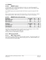
A.3.18.2
King Serial DME Interface
Pin Name
Connector
Pin
I/O
KING SERIAL DME CLOCK
P602
18
Out
KING SERIAL DME DATA
P602
19
Out
KING SERIAL RNAV REQUEST
P602
20
In
KING SERIAL RNAV MODE
P602
21
In
MAIN KING SERIAL DME DATA
P606
59
I/O
MAIN KING SERIAL DME CLOCK
P606
60
I/O
MAIN KING SERIAL DME HOLD OUT
P606
61
Out
MAIN KING SERIAL DME REQUEST
P606
62
I/O
MAIN KING SERIAL DME ON OUT
P606
63
Out
MAIN KING SERIAL RNAV REQUEST
P606
64
In
These pins are used when the GIA 63W is configured for King Serial DME tuning.
Input logic levels are:
High 6.5 VDC or greater
Low
3.5 VDC or less


