


Page 15-50
G900X/G950 Installation and Maintenance Manual – Software, Configuration, and Calibration
Revision D
190-00719-00
15.4.4.3 GMA Annunciator Parameters (arrow light beneath keys)
BRIGHTNESS
: Depicts actual brightness level of the arrow lights beneath the keys on the GMA. Range
is between 0.0 and 99.99.
GAIN
: Controls the brightness level of the arrow lights beneath the keys on the GMA. Range is between
0 and 2. Gain is a brightness multiplier and is best suited for small adjustments.
OFFSET
: Allows an offset control of the brightness level for the arrow lights beneath the keys on the
GMA. Range is between -100 and 100. Offset allows for the largest change in brightness in efforts to
match other cockpit lighting.
15.4.4.4 GMA
Key
Parameters
BRIGHTNESS
: Depicts actual brightness level of the keys on the GMA. Range is between 0.0 and
99.99.
GAIN
: Controls the brightness level of the keys on the GMA. Range is between 0 and 2. The gain is a
multiplier that lends itself best to small adjustments, mainly used for tweaking the brightness.
OFFSET
: Allows an offset control of the brightness level for the keys on the GMA. Range is between -
100 and 100. Offset allows for the largest change in brightness in efforts to match other cockpit lighting.
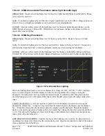
Figure 15-34. Dimmer Bus Lighting
When the lighting input source is set to use dimmer bus voltage (14 VDC, 28 VDC, 5 VDC), installers
can set a transition point where the display switches from using dimmer bus voltage to using the
photocell. The light green curve represents the selected input. If something other than photo input is
used, the light-green curve will represent that input, while the dark-green input will represent the photo
input.
PHOTO TRANSITION %
: Sets the input level point at which the display transitions from using the
photocell to dimmer bus. At input levels greater than the transition point, the display uses the dimmer
bus. At input levels less than the transition point, the display uses the photocell. Should the installer
desire to completely operate the display entirely on dimmer bus voltage, the transition point should be set
to 0.0. This allows the brightness to track the full range of the dimmer bus voltage from the maximum
input value to the minimum value.
EDIT PHOTO CURVE VERTEX
: Controls the slopes of the lighting curve used by the photocell when
the dimmer bus input level falls below the set transition point. Operation is identical to that of the normal
vertex adjustment described above.