Page A-40
G900X/G950 Installation and Maintenance Manual – Pinouts
Revision D
190-00719-00
A.3.15.4 Flag
Pin Name
Connector
Pin
I/O
VOR/LOC +FLAG
P602
3
Out
VOR/LOC -FLAG (VOR/LOC COMMON)
P602
4
--
GLIDFLAG
P602
32
Out
GLIDESLOPE -FLAG (GLIDESLOPE COMMON)
P602
53
--
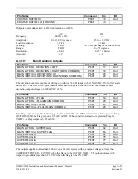
The Flag output is capable of driving up to three 1000
Ω
meter loads. When valid information is present
(Flag OUT OF VIEW) the Flag output is 375 ±80 mVDC
.
When invalid information is present (Flag IN
VIEW) the Flag output is 0 ±25 mVDC
.
A.3.15.5 OBS
Pin Name
Connector
Pin
I/O
VOR OBS ROTOR C
P602
9
Out
VOR OBS ROTOR H (GROUND)
P602
10
--
VOR OBS STATOR E (VOR/LOC COMMON)
P602
11
--
VOR OBS STATOR F
P602
12
In
VOR OBS STATOR D
P602
13
In
VOR OBS STATOR G (VOR/LOC COMMON)
P602
14
--
VOR OBS ROTOR C and H are a buffered 500 Hz output that is intended to drive the OBS rotors. VOR
OBS STATOR D and VOR OBS STATOR F are each phase and amplitude shifted version of the VOR
ROTOR C output. Each pair is intended to read one of the two windings of the indicator’s OBS stator.
A.3.15.6 VOR/LOC
Composite
Pin Name
Connector
Pin
I/O
VOR/LOC COMPOSITE OUT
P602
8
Out
With a Standard VOR Test Signal applied, VOR/LOC COMPOSITE OUT is 0.5 ±0.1 V
RMS
into a 10 k
Ω
load. With a Standard Localizer Centering Test Signal applied, VOR/LOC COMPOSITE OUT is 0.350
±0.05 V
RMS
into a 10 k
Ω
load.
A.3.15.7 ILS
Energize
Pin Name
Connector
Pin
I/O
ILS ENERGIZE
P602
29
Out
INACTIVE: Floating (can be pulled up to externally sourced Vout in the range 0
≤
Vout
≤
33VDC)
Leakage current in the INACTIVE state is typically
≤
10 uA to ground
ACTIVE: Vout
≤
0.5VDC with
≤
20 mA sink current
Sink current must be externally limited to 20 mA max


