G900X/G950 Installation and Maintenance Manual – Software, Configuration, and Calibration
Page 15-49
190-00719-00
Revision D
RESPONSE TIME:
Adjusts the speed, in seconds, that the brightness level responds to input level (bus
voltage or ambient light) changes. Adjustable range is between 0 to 9 seconds. A higher number yields a
greater delay in response. For testing purposes it might prove beneficial to set the response time to 0, or a
low value, to see immediate reaction to an input stimulus.
MINIMUM
: Sets the minimum display brightness. Adjustable range is between 0.14 to 99.99. The
higher the number, the greater the minimum brightness. Display brightness will not decrease below the
set minimum, regardless of input value or slope. The minimum needs to be set to avoid the input from
going too low and experiencing display flicker caused by difficulties of lighting bulbs at low inputs.
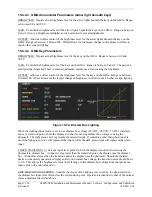
EDIT CURVE VERTEX:
Selects which point (vertex) on the lighting curve to adjust. See Figure 15-27.
By adjusting the vertices, the lighting curve slope(s) can be adjusted as functions of a single curve. This
sets the brightness level for any given input level. When a point is selected for adjustment, the
map-panning joystick on the PFD/MFD is used to manipulate the point.
Selection Description
NONE
No vertex point is selected.
1
The #1 vertex (bottom endpoint of curve) is selected for adjustment. This
point cannot be moved in the vertical (y) direction. It is only adjustable in
the horizontal (right/left) direction.
2
The #2 vertex is selected for adjustment.
3
The #3 vertex is selected for adjustment.
4
The #4 vertex (top endpoint of curve) is selected for adjustment. This
point cannot be moved in the vertical (y) direction. It is only adjustable in
the horizontal (right/left) direction.
ALL
All vertex points are selected for adjustment. Movement is only allowed
within each respective bound of a vertex (vertex #1 and #2, the curve
endpoints, can not move vertically). The most pronounced resultant
movements would be a step or trough shaped curve.
#4 Vertex (Maximum)
#3 Vertex
#2 Vertex
#1 Vertex (Minimum)
Brightness Level Follows
Lighting Curve/Input Level Intersection
Intersection of Input Level,
Lighting Curve,
and Brightness Level
Minimum Brightness
(Red Line)
Input Level Line
(Photocell or
Dimmer Bus Input)
Selected Vertex Points Are
Adjusted Using the Map-Panning
Joystick
Figure 15-33. Lighting Curve Vertices


