


Page B-42
Airframe Specific Installation Instructions (G900X Only) – G900X/G950 Installation and Maintenance Manual
Revision D
190-00719-00
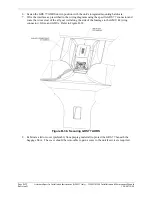
5.
The GRS 77 must be aligned with the aircraft’s heading. To do this draw out parallel dimensions
using the aft edge of the wing spar and the elevator torque tube cover.
6.
Mark the center of the first and second hole using the dimensions shown in Figure B-54.
7.
Once these holes are marked place the GRS 77 mount to intersect at each location and then trace
out the remaining bracket outline and holes.
C
L
LOCATE SECOND HOLE
APPROXIMATELY AS SHOWN
LOCATE FIRST HOLE
APPROXIMATELY AS SHOWN
115-00909-00
ANGLE BRACKET (REF)
(2 REQ'D)
Figure B-54. GRS 77 Angle Bracket Fastener Locations