Displaying a Network Topology View
EPICenter Reference Guide
285
Map Elements
The following elements can appear on a map:
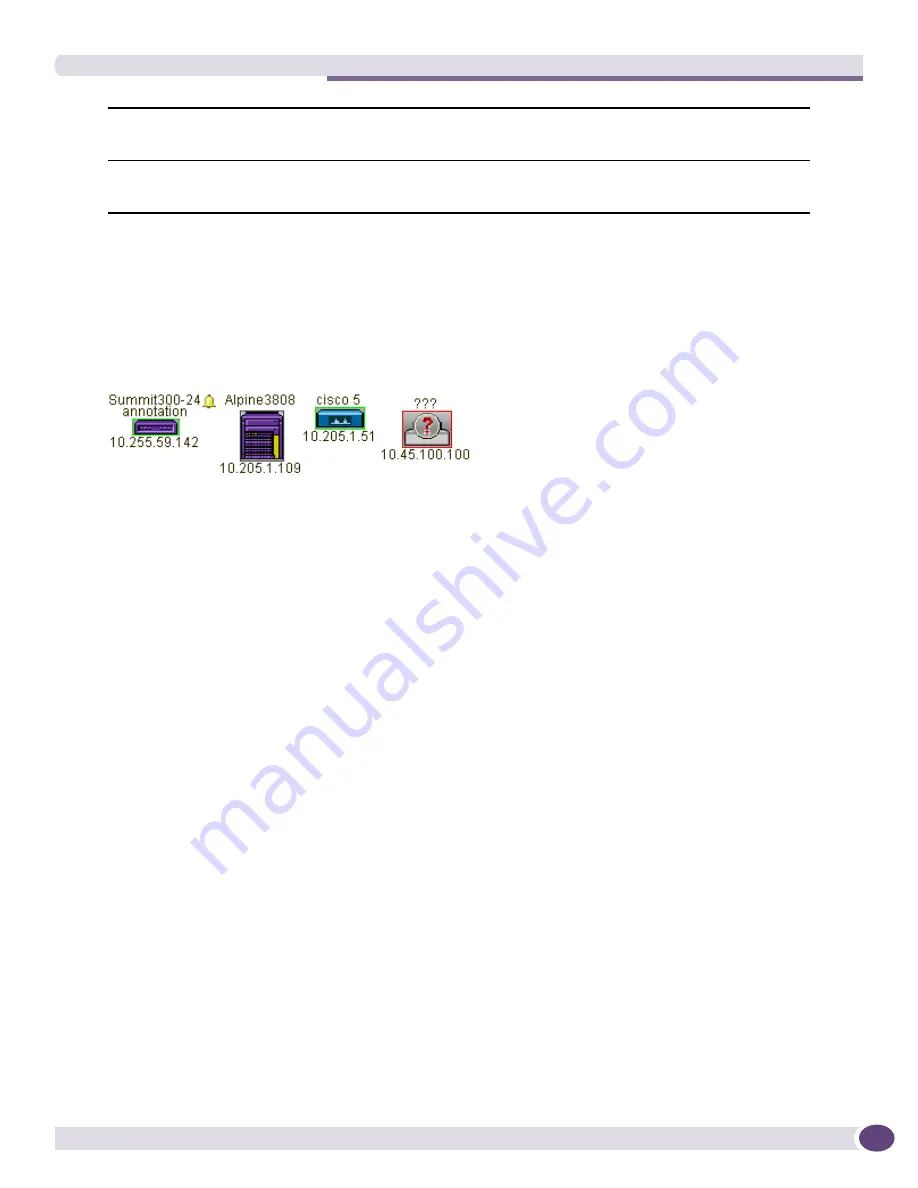
Device Nodes.
Device nodes represent the managed devices found in EPICenter’s Inventory data base.
Figure 129: Example of device nodes, including an unknown device type
A device node shows the following information:
●
The name of the device as it is kept in the Inventory database (this can be hidden using View or
Map properties).
●
An optional, user-supplied annotation for the node.
●
A small icon representing the specific device or device product line, as shown in
Figure 129
. If the
device is of an “unknown” type, an unknown device icon (a circle with a question mark) is
displayed. The device icon can be hidden using View or Map properties.
●
The device’s IP address.
●
The device alarm status, indicated by the presence of an alarm icon (small bell). The alarm status
shows the highest level alarm currently unacknowledged for the device. The color of the bell
indicates the severity of the alarm.
If no icon appears, then either there are no unacknowledged alarms for the device, or the alarm
status is below the alarm status threshold for the view. The alarm status threshold is set when you
create a View, or in the View properties, and specifies the lowest severity level at which an alarm
status icon should be displayed for a device node on the map.
If the alarm icon has an “X” through it, this means alarm propagation has been disabled for this
device; the alarm status of this device does not influence the aggregate alarm status displayed for the
map in which this node is located.
●
The device status, indicated by the color of the icon border.
■
A green border indicates that the device is up.
■
A red border indicates that the device is down.
■
A gray border indicates that the device is offline.
Each managed device known to EPICenter can only appear once in each topological view.
Submap Nodes.
A submap node represents a child map of the current map.
Map Element Description
panel
The bottom portion of the left-hand panel, where information about the currently
selected map element is displayed, if one (and only one) is selected. Otherwise, the
panel is empty.
Currently selected map
The main panel of the Topology Viewer. It shows the currently selected map (or
submap) in the current topology view. Only one view and map can be displayed at a
time.
Содержание EPICenter 6.0
Страница 14: ...EPICenter Reference Guide 14 ...
Страница 18: ...Preface EPICenter Reference Guide 18 ...
Страница 19: ...1 EPICenter Basic Features ...
Страница 20: ......
Страница 24: ...EPICenter Overview EPICenter Reference Guide 24 ...
Страница 44: ...Getting Started with EPICenter EPICenter Reference Guide 44 ...
Страница 100: ...The Inventory Manager EPICenter Reference Guide 100 ...
Страница 140: ...The EPICenter Alarm System EPICenter Reference Guide 140 ...
Страница 172: ...Configuration Manager EPICenter Reference Guide 172 ...
Страница 196: ...The Firmware Manager EPICenter Reference Guide 196 ...
Страница 220: ...The Interactive Telnet Feature EPICenter Reference Guide 220 ...
Страница 250: ...The Grouping Manager EPICenter Reference Guide 250 ...
Страница 276: ...Real Time Statistics EPICenter Reference Guide 276 ...
Страница 295: ...The New Menu EPICenter Reference Guide 295 Figure 137 Example of a default layout for a 500 node map ...
Страница 342: ...Using the VLAN Manager EPICenter Reference Guide 342 ...
Страница 348: ...The ESRP Monitor EPICenter Reference Guide 348 ...
Страница 446: ...EPICenter Reports EPICenter Reference Guide 446 ...
Страница 447: ...2 Advanced Upgrade Features ...
Страница 448: ......
Страница 480: ...EAPS Protocol Monitoring and Verification EPICenter Reference Guide 480 ...
Страница 508: ...Using the Policy Manager EPICenter Reference Guide 508 ...
Страница 525: ...3 Appendices ...
Страница 526: ......
Страница 542: ...EPICenter Backup EPICenter Reference Guide 542 ...
Страница 564: ...Voice over IP Manager EPICenter Reference Guide 564 ...
Страница 580: ...EPICenter Reference Guide 580 ...


