A
B
C
D
E
F
G
H
L
M
N
P
Uso e manutenzione
Use and Maintenance operations
sezione / section
D 5
66
999R Aggiornamento/Update
- M.Y. 2006 - edizione/edition 00
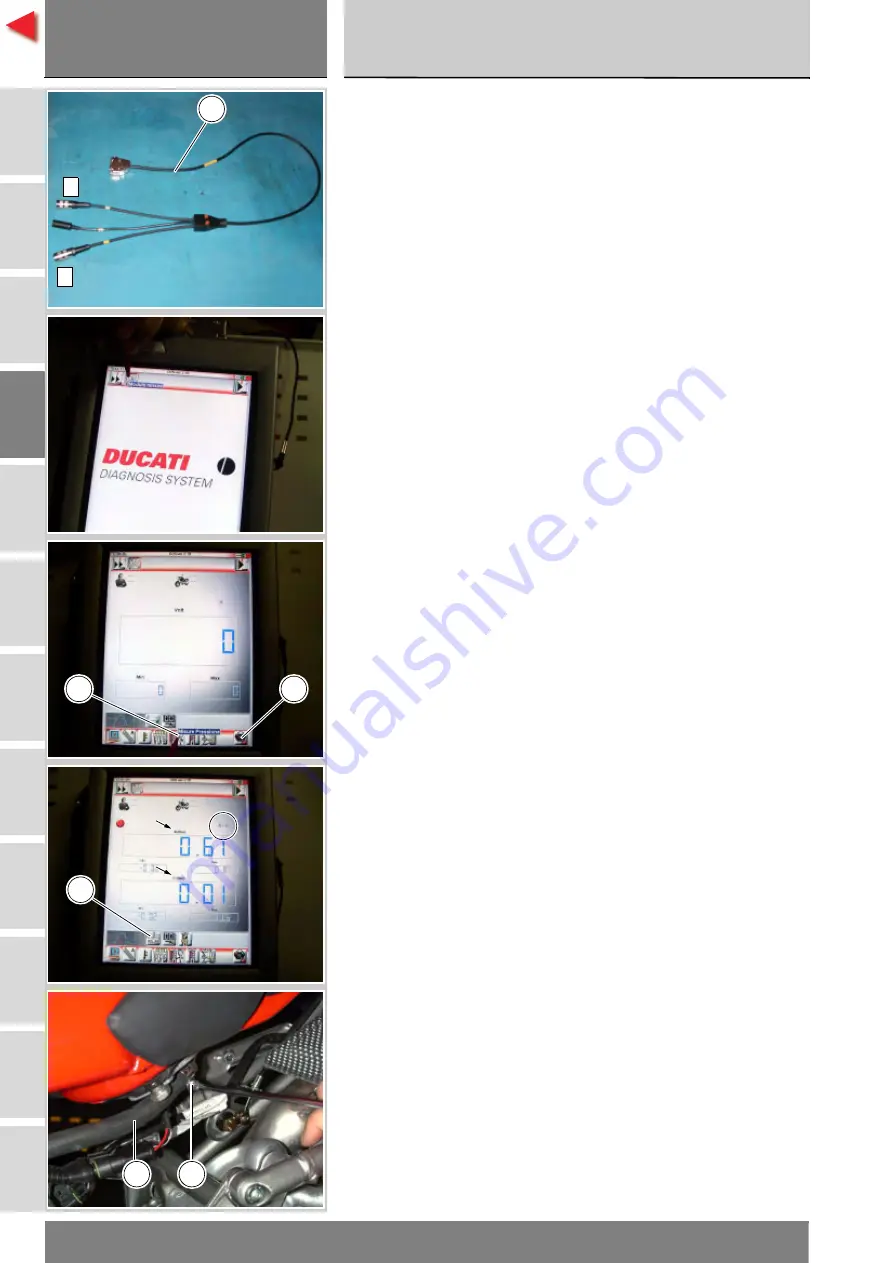
Sullo strumento DDS (1) selezionare
la funzione “Modulo misure”,
premendo sull'icona “Modulo
misure”; poi premere l'icona
“Misure Pressione” (L) e di seguito
l'icona di “Start” (M).
Nella schermata viene indicata con
una lettera maiuscola quale presa
utilizzare del cavo (Modulo Misure) (3):
A, B oppure C.
Esistono tre tipi di visualizzazione dei
valori: una in forma numerica e due in
forma grafica; per selezionare una
tipologia o l'altra, premere l'icona
“Visualizzazione valori” (N).
Il valore rilevato è quello indicato in
corrispondenza della lettera (A) o (C)
che identifica il cavo utilizzato per
il rilevamento: ossia se si utilizza
la presa (A) del cavo (3) il valore
rilevato sarà quello corrispondente
alla lettera (A) nella videata.
La pressione massima deve essere
uguale a
3
bar (nominale).
Finita la prova, rimuovere i
componenti dello strumento di
diagnosi, rimontare il tubo (D)
mandata serbatoio fissandolo con
fascetta (E).
Rimontare l’assieme serbatoio – sella
– codone (Sez. E 3).
On the DDS tester (1), select the
“Measurement module” function by
pressing the corresponding icon; then
press the “Pressure Test” icon (L)
followed by the “Start” icon (M).
The socket to which the cable
(Measurement Module) (3) is to be
connected is indicated on the screen
with a capital letter: A, B or C.
The values may be displayed in three
different ways: in one numeric form
and in two graphic forms; to select
the desired display type, press the
“Value display” icon (N).
The value measured is that indicated
next to the letter (A) or (C), which
identifies the cable used for the
measurement: i.e. if you used
connector (A) of the cable (3), the
value measured will be displayed next
to the letter (A) on the screen.
The maximum pressure must be
3
bar (nominal).
On completion of the test, remove
all the components of the test
instrument, refit the fuel tank outlet
pipe (D) securing it with the clamp (E).
Refit the fuel tank – seat – tail guard
assembly (Sect. E 3).
A
C
3
M
L
N
D
E
Содержание 999R 2006
Страница 11: ...A B C D E F G H L M N P Generalit 0 Description 0...
Страница 25: ...A B C D E F G H L M N P Informazioni sul modello 0 Model specific information 0...
Страница 29: ...A B C D E F G H L M N P Caratteristiche tecniche 0 Specifications 0...
Страница 73: ...A B C D E F G H L M N P Uso e manutenzione 0 Use and Maintenance operations 0...
Страница 150: ......
Страница 151: ...A B C D E F G H L M N P Vestizione 0 Fairing 0...
Страница 169: ...Vestizione Fairing sezione section E 3 19 999R Aggiornamento Update M Y 2006 edizione edition 00 A B C D E F G H L M N P...
Страница 172: ......
Страница 173: ...A B C D E F G H L M N P Comandi Dispositivi 0 Controls Devices 0...
Страница 199: ...A B C D E F G H L M N P Ruote Sospensioni Freni0 Wheels Suspensions Brakes 0...
Страница 246: ......
Страница 247: ...A B C D E F G H L M N P Mototelaio 0 Frame 0...
Страница 272: ......
Страница 273: ...A B C D E F G H L M N P Impianto di alimentazione Scarico 0 Fuel system Exhaust system 0...
Страница 305: ...A B C D E F G H L M N P Impianto iniezione accensione 0 Ignition injection system 1...
Страница 330: ......
Страница 331: ...A B C D E F G H L M N P Motore 0 Engine 1...
Страница 370: ...Motore Engine sezione section N 3 2 40 A B C D E F G H L M N P 999R Aggiornamento Update M Y 2006 edizione edition 00...
Страница 371: ...Motore Engine sezione section N 3 2 41 A B C D E F G H L M N P 999R Aggiornamento Update M Y 2006 edizione edition 00...
Страница 510: ......
Страница 511: ...A B C D E F G H L M N P Impianto elettrico 0 Electric system 0...
Страница 596: ......
Страница 597: ...A B C D E F G H L M N P Indice degli argomenti 0 Subject index 0...


