


4-52
Section 4 Boat Systems
Once the system has been disch arged, the power
to the diesel generator and the blower fan will be cu t.
This ensures that the co mpartment will be “ soake d”
with e tinguishant. nce the danger of fire has been
extinguished, the toggle switch ca n be moved from
“ NORM AL ” to “ OV E RRID E .” This will allow power to the
diesel generator and the blower fan.
It is recommended that the fire suppression tank be
weighed on an accu
rate sca le every six ( 6 ) months.
There is a ch art in the manufact urer’ s operation manual
that lists the weight of the ca nister and co ntents.
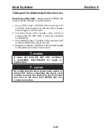
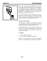
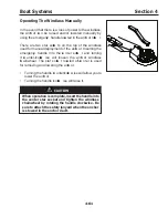
Manual O verride System
The automatic fire e tinguisher can be activated manually
by pulling the manual override handle loca ted next to the
leaning post breake r panel below the helm seat.
E arly detect ion and use of the manual override system
will reduce fire damage by eliminating the time necessary
for heat in the bilge to rise sufficiently to activate the
automatic fire system.
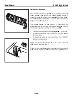
T o O p erate
1 . P ull pin secu ring the handle.
2 . P ull red F IRE handle q uickl
y and briskl y.
Refer to the manufact urer’ s manual in the operator’ s
packe
t for co mplete instruct ions and warranty information.
F
I
R
E
REMOVE PIN
PULL HANDLE
FOR MANU
AL OPER
ATION
Содержание 37 Justice Series
Страница 24: ...Section 1 Safety 1 12 O p erator s Notes...
Страница 56: ...Section 2 Boat O p eration 2 32 O p erator s Notes...
Страница 60: ...3 4 Section 3 F uel System Diesel F uel System Diagram F O RWARD...
Страница 61: ...3 5 F uel System Section 3 Gasoline F uel System Diagram F O RWARD...
Страница 74: ...4 2 Section 4 Boat Systems...
Страница 75: ...4 3 Boat Systems Section 4...
Страница 76: ...4 4 Section 4 Boat Systems...
Страница 77: ...4 5 Boat Systems Section 4...
Страница 78: ...4 6 Section 4 Boat Systems...
Страница 107: ...4 35 Boat Systems Section 4 F O RWARD...
Страница 134: ...4 62 Section 4 Boat Systems O p erator s Notes...
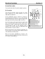
Страница 145: ...5 11 Electrical Systems Section 5 Main DC Breaker Panel...
Страница 146: ...5 12 Section 5 Electrical Systems Main AC Breaker Panel...
Страница 148: ...5 14 Section 5 Electrical Systems H elm Breaker Panel...
Страница 149: ...5 15 Electrical Systems Section 5 L eaning Post Breaker Panel...
Страница 150: ...5 16 Section 5 Electrical Systems Battery Switch Breaker Panel...
Страница 155: ...5 21 Electrical Systems Section 5 Battery System Diagram...
Страница 156: ...5 22 Section 5 Electrical Systems Battery Switch Panel Diagram...
Страница 157: ...5 23 Electrical Systems Section 5 H elm Breaker Panel Diagram...
Страница 158: ...5 24 Section 5 Electrical Systems H elm Switch Panel Diagram...
Страница 159: ...5 25 Electrical Systems Section 5 L eaning Post Switch Panel Diagram...
Страница 160: ...5 26 Section 5 Electrical Systems L ighting Schematic Deck...
Страница 161: ...5 27 Electrical Systems Section 5 Windlass Schematic...
Страница 162: ...5 28 Section 5 Electrical Systems O verb oard Discharge Panel and H olding T ank Schematic...
Страница 163: ...5 29 Electrical Systems Section 5 DC Distrib ution Panel...
Страница 164: ...5 30 Section 5 Electrical Systems DC Wiring Schematic Cab in...
Страница 165: ...5 31 Electrical Systems Section 5 H ardtop Schematic...
Страница 166: ...5 32 Section 5 Electrical Systems 120 0 Shore ower Schematic...
Страница 167: ...5 33 Electrical Systems Section 5 AC Distrib ution Panel 120 0...
Страница 168: ...5 34 Section 5 Electrical Systems 220 0 Shore ower Schematic...
Страница 169: ...5 35 Electrical Systems Section 5 AC istribution anel 220 0...
Страница 170: ...5 36 Section 5 Electrical Systems Bow T hruster Schematic...
Страница 171: ...5 37 Electrical Systems Section 5 Bilge Wiring Schematic...
Страница 172: ...5 38 Section 5 Electrical Systems Stereo Schematic...
Страница 178: ...5 44 Section 5 Electrical Systems O p erator s Notes...
Страница 212: ...6 34 Section 6 Maintenance Operator s Notes...
Страница 214: ......