4-45
Boat Systems
Section 4
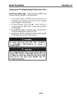
T esting and T roub leshooting Before Each U se
Normal O p erating State
- S ensing device GRE E N L E D
is ON and ci rcu it breake r is at ON position.
1 .
Press TEST button. GREEN LED should go
T
and RE D L E D should co me ON and ci rcu it breake r
should trigger to OF F position.
2 . If sensing device L E D or breake r does not trip or
change state D N T SE. Consult an electrician
for assistance .
3 . P ress RE S E T button. The RE D L E D should turn OF F
and the GRE E N L E D should turn ON.
4 .
MAN ALLY RESET (SWITCH) CIRC IT BREA ER
to ON position to restore ci rcu it power.
If ab ove test fails, DO NO T U SE. CO NSU L T
A Q U AL IF IED EL ECT RICIAN for rep air or
rep lacement.
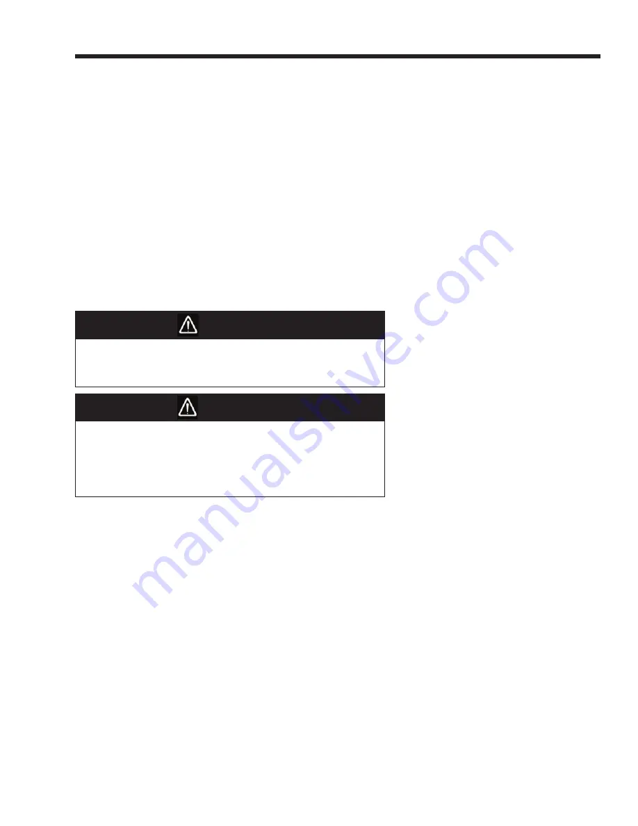
Be certain that the shore p ower main switch is
turned O F F b efore connecting the p ower cord
cordset. Connect the cordset to the b oat inlet
rst, then to the shore inlet. NE E alter the
cordset connectors.
WARNING
CAU T IO N
Содержание 37 Justice Series
Страница 24: ...Section 1 Safety 1 12 O p erator s Notes...
Страница 56: ...Section 2 Boat O p eration 2 32 O p erator s Notes...
Страница 60: ...3 4 Section 3 F uel System Diesel F uel System Diagram F O RWARD...
Страница 61: ...3 5 F uel System Section 3 Gasoline F uel System Diagram F O RWARD...
Страница 74: ...4 2 Section 4 Boat Systems...
Страница 75: ...4 3 Boat Systems Section 4...
Страница 76: ...4 4 Section 4 Boat Systems...
Страница 77: ...4 5 Boat Systems Section 4...
Страница 78: ...4 6 Section 4 Boat Systems...
Страница 107: ...4 35 Boat Systems Section 4 F O RWARD...
Страница 134: ...4 62 Section 4 Boat Systems O p erator s Notes...
Страница 145: ...5 11 Electrical Systems Section 5 Main DC Breaker Panel...
Страница 146: ...5 12 Section 5 Electrical Systems Main AC Breaker Panel...
Страница 148: ...5 14 Section 5 Electrical Systems H elm Breaker Panel...
Страница 149: ...5 15 Electrical Systems Section 5 L eaning Post Breaker Panel...
Страница 150: ...5 16 Section 5 Electrical Systems Battery Switch Breaker Panel...
Страница 155: ...5 21 Electrical Systems Section 5 Battery System Diagram...
Страница 156: ...5 22 Section 5 Electrical Systems Battery Switch Panel Diagram...
Страница 157: ...5 23 Electrical Systems Section 5 H elm Breaker Panel Diagram...
Страница 158: ...5 24 Section 5 Electrical Systems H elm Switch Panel Diagram...
Страница 159: ...5 25 Electrical Systems Section 5 L eaning Post Switch Panel Diagram...
Страница 160: ...5 26 Section 5 Electrical Systems L ighting Schematic Deck...
Страница 161: ...5 27 Electrical Systems Section 5 Windlass Schematic...
Страница 162: ...5 28 Section 5 Electrical Systems O verb oard Discharge Panel and H olding T ank Schematic...
Страница 163: ...5 29 Electrical Systems Section 5 DC Distrib ution Panel...
Страница 164: ...5 30 Section 5 Electrical Systems DC Wiring Schematic Cab in...
Страница 165: ...5 31 Electrical Systems Section 5 H ardtop Schematic...
Страница 166: ...5 32 Section 5 Electrical Systems 120 0 Shore ower Schematic...
Страница 167: ...5 33 Electrical Systems Section 5 AC Distrib ution Panel 120 0...
Страница 168: ...5 34 Section 5 Electrical Systems 220 0 Shore ower Schematic...
Страница 169: ...5 35 Electrical Systems Section 5 AC istribution anel 220 0...
Страница 170: ...5 36 Section 5 Electrical Systems Bow T hruster Schematic...
Страница 171: ...5 37 Electrical Systems Section 5 Bilge Wiring Schematic...
Страница 172: ...5 38 Section 5 Electrical Systems Stereo Schematic...
Страница 178: ...5 44 Section 5 Electrical Systems O p erator s Notes...
Страница 212: ...6 34 Section 6 Maintenance Operator s Notes...
Страница 214: ......


