Measured input
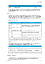
Function block uses analog current and voltage measurements and calculated phase-to-phase or
phase-to-ground loop impedances.
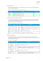
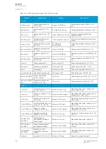
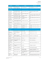
Table. 5.5.4 - 224. Measurement inputs of the 21FL function.
Signals
Description
Time base
VT1 U1, U2, U3
The line-to-neutral or line-to-line voltages of the first voltage transformer module.
5ms
CT1 IL1, IL2, IL3
The measurements of the phase currents L1 (A), L2 (B) and L3 (C).
5ms
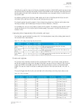
Fault locator triggering
The "Trig fault locator" input defines which signal triggers the fault locator. This can be any binary signal
generated by the unit. Typically, a TRIP signal of a protection function or the "Open" status of the
breaker is used as the triggering input.
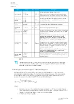
Several conditions have to be met before the fault locator can trigger and record the distance to a fault.
First, when receiving a triggering signal, the function checks if the calculation is blocked. The
calculation blocking signals are determined by the "Block calculation" matrix set by the user. Next, the
function checks if any phase-to-earth voltages are available. If there are no available voltages, the
function can only record phase-to-phase impedance loops. If there are available voltages, the function
can also record phase-to-neutral impedance loops. Depending on the measured phase currents at the
moment the triggering signal was received, the recorded impedance loop is selected from the available
options. See the table "Required current conditions" for more information on which conditions have to
be met to trigger impedance recording.
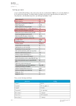
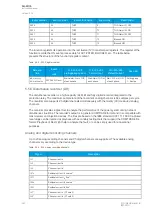
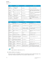
Table. 5.5.4 - 225. Pick-up settings.
Name
Range
Step
Default
Description
Trigger
current>
0.0…40.0×I
n
0.1×I
n
1×I
n
Sets the trigger current. Affects which impedance loop is recorded, if
anything is recorded at all (see the table below).
Reactance
per km
0.000…5.000
Ω
/
km
0.001
Ω
/
km
0.125
Ω
/
km
This setting helps calculate the distance to a fault.
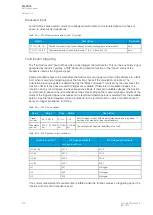
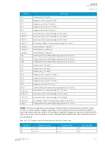
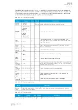
Table. 5.5.4 - 226. Required current conditions.
Currents over limit
P-E voltages available
P-E voltages not available
Recorded impedance
IL1, IL2, IL3
XL12
XL12
IL1, IL2
XL12
XL12
IL2, IL3
XL23
XL23
IL1, IL3
XL31
XL31
IL1
XL1
No trigger
IL2
XL2
No trigger
IL3
XL3
No trigger
If no current measurement requirements are fulfilled when the function receives a triggering signal, the
function will not record impedance at all.
A
AQ
Q-F205
-F205
Instruction manual
Version: 2.04
334
© Arcteq Relays Ltd
IM00013
Содержание AQ F205
Страница 1: ...AQ F205 Feeder protection IED Instruction manual ...
Страница 2: ......
Страница 379: ...Figure 7 4 245 Example block scheme A AQ Q F205 F205 Instruction manual Version 2 04 Arcteq Relays Ltd IM00013 377 ...
Страница 389: ...Figure 8 7 254 Device installation A AQ Q F205 F205 Instruction manual Version 2 04 Arcteq Relays Ltd IM00013 387 ...

