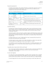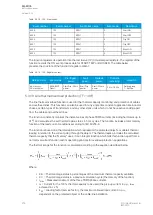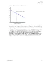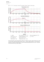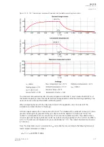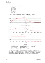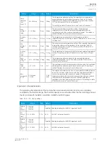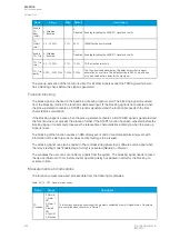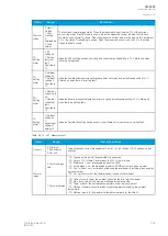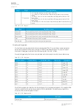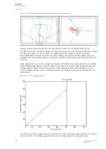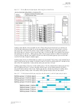
Figure. 5.3.19 - 162. Thermal image response with maximum load (installation according presumptions).
The maximum allowed load results in the end temperature of 89.68
̊
C which means that 99.57 % of
the thermal capacity is used. This result matches the expectations of the thermal image perfectly. The
user can now securely set the cable's overheating alarm.
When comparing the result to the fully-tuned model in the application, let us include all of the
installation correction factors to the image.
A 66 kV copper cable with a cross-section of 500 mm
2
is installed
with no adjacent cables (k=1) into a
ground consisting of dry gravel and clay (k=0.85) and into the depth of 1.5 meters (k=0.95). The
cable's 1 s permissible short-circuit current is 71.4 kA and its insulation is XLPE. The cable's screen
circuit is open and the laying formation is flat. Its current-carrying capacity is 575 A in 65
̊
C and 680 A
in 90
̊
C. The reference temperature for ground installation is 15
̊
C. The cable's thermal time constant
is 183.8 min.
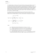
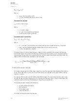
From this initial data one can calculate the k
SF
correction factor according to the following formula (k
factor related information in italics):
A
AQ
Q-F205
-F205
Instruction manual
Version: 2.04
© Arcteq Relays Ltd
IM00013
227
Содержание AQ F205
Страница 1: ...AQ F205 Feeder protection IED Instruction manual ...
Страница 2: ......
Страница 379: ...Figure 7 4 245 Example block scheme A AQ Q F205 F205 Instruction manual Version 2 04 Arcteq Relays Ltd IM00013 377 ...
Страница 389: ...Figure 8 7 254 Device installation A AQ Q F205 F205 Instruction manual Version 2 04 Arcteq Relays Ltd IM00013 387 ...


