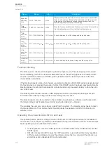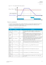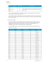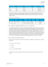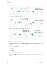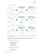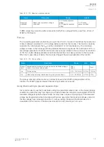
Table. 5.3.11 - 112. Setting parameters for operating time characteristics.
Name
Range
Step
Default
Description
Delay type 1: DT
2: IDMT
-
1: DT
Selection of the delay type time counter. The selection possibilities are
dependent (IDMT, Inverse Definite Minimum Time) and independent
(DT, Definite Time) characteristics.
Definite
operating
time delay
0.000…1800.000s 0.005s 0.040s
Definite time operating delay. This setting is active and visible when DT
is the selected delay type.
When set to 0.000 s, the stage operates as instant stage without added
delay. When the parameter is set to 0.005...1800 s, the stage operates
as independent delayed.
Time dial
setting k
0.01…60.00s
0.01s
0.05s
This setting is active and visible when IDMT is the selected delay type.
Time dial/multiplier setting for IDMT characteristics.
IDMT
Multiplier
0.01…25.00s
0.01s
1.00s
This setting is active and visible when IDMT is the selected delay type.
IDMT time multiplier in the U
m
/U
set
power.
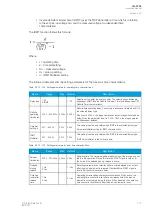
Table. 5.3.11 - 113. Setting parameters for reset time characteristics.
Name
Range
Step
Default
Description
Release
time delay
0.000…150.000s 0.005s 0.06s
Resetting time. The time allowed between pick-ups if the pick-up has not
led to a trip operation. During this time the START signal is held on for
the timers if the delayed pick-up release is active.
Delayed
pick-up
release
1: No
2: Yes
-
2: Yes
Resetting characteristics selection, either time-delayed or instant after
the pick-up element is released. If activated, the START signal is reset
after a set release time delay.
Time calc
reset after
release
time
1: No
2: Yes
-
2: Yes
Operating timer resetting characteristics selection. When actived, the
operating time counter is reset after a set release time if the pick-up
element is not activated during this time. When disabled, the operating
time counter is reset directly after the pick-up element reset.
Continue
time
calculation
during
release
time
1: No
2: Yes
-
1: No
Time calculation characteristics selection. If activated, the operating time
counter continues until a set release time even when the pick-up
element is reset.
The user can reset characteristics through the application. The default setting is a 60 ms delay; the
time calculation is held during the release time.
In the release delay option the operating time counter calculates the operating time during the release.
When using this option the function does not trip if the input signal is not re-activated while the release
time count is on-going.
Events and registers
The undervoltage function (abbreviated "UV" in event block names) generates events and registers
from the status changes in START, TRIP, and BLOCKED. The user can select which event messages
are stored in the main event buffer: ON, OFF, or both. The function offers four (4) independent stages;
the events are segregated for each stage operation.
The events triggered by the function are recorded with a time stamp and with process data values.
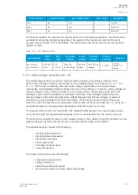
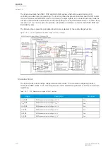
Table. 5.3.11 - 114. Event codes.
Event number
Event channel
Event block name
Event code
Description
5696
89
UV1
0
Start ON
A
AQ
Q-F205
-F205
Instruction manual
Version: 2.04
© Arcteq Relays Ltd
IM00013
179
Содержание AQ F205
Страница 1: ...AQ F205 Feeder protection IED Instruction manual ...
Страница 2: ......
Страница 379: ...Figure 7 4 245 Example block scheme A AQ Q F205 F205 Instruction manual Version 2 04 Arcteq Relays Ltd IM00013 377 ...
Страница 389: ...Figure 8 7 254 Device installation A AQ Q F205 F205 Instruction manual Version 2 04 Arcteq Relays Ltd IM00013 387 ...


