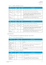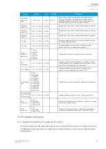
Name
Range
Step
Default
Description
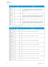
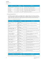
U4 Res/SS VT
primary
1…1000000V
0.1V
20000.0V The primary nominal voltage of the connected U0 or SS VT.
U4 Res/SS VT
secondary
0.2…400V
0.1V
100.0V
The secondary nominal voltage of the connected U0 or SS VT.
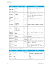
U1 Polarity
0: -
1: Invert
-
0: -
The selection of the first voltage measurement channel's (U1) polarity
(direction). The default setting is for the positive voltage to flow from
connector 1 to connector 2, with the secondary voltage's starpoint
pointing towards the line.
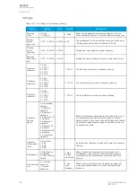
U2 Polarity
0: -
1: Invert
-
0: -
The selection of the second voltage measurement channel's (U2)
polarity (direction). The default setting is for the positive voltage to
flow from connector 1 to connector 2, with the secondary voltage's
starpoint pointing towards the line.
U3 Polarity
0: -
1: Invert
-
0: -
The selection of the third voltage measurement channel's (U3) polarity
(direction). The default setting is for the positive voltage to flow from
connector 1 to connector 2, with the secondary voltage's starpoint
pointing towards the line.
U4 Polarity
0: -
1: Invert
-
0: -
The selection of the fourth voltage measurement channel's (U4)
polarity (direction). The default setting is for the positive voltage to
flow from connector 1 to connector 2, with the secondary voltage's
starpoint pointing towards the line.
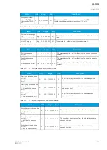
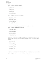
VT scaling
factor P/S
-
-
-
A relay feedback value; the calculated scaling factor that is the ratio
between the primary voltage and the secondary voltage.
VT scaling
factor p.u. Pri
-
-
-
A relay feedback value; the scaling factor for the primary voltage's
per-unit value.
VT scaling
factor p.u. Sec -
-
-
A relay feedback value; the scaling factor for the secondary voltage's
per-unit value.
U3 VT scaling
factor P/S U0/
SS
-
-
-
A relay feedback value; the scaling factor that is the ratio between the
U3 channel's primary and secondary voltages. This setting is only
valid if the "2LL+U3+U4" mode is selected.
U3 scaling
factor p.u. Pri
-
-
-
A relay feedback value for channel U3; the scaling factor for the
primary voltage's per-unit value. This setting is only valid if the
"2LL+U3+U4" mode is selected.
U3 scaling
factor p.u. Sec -
-
-
A relay feedback value for channel U3; the scaling factor for the
secondary voltage's per-unit value. This setting is only valid if the
"2LL+U3+U4" mode is selected.
U4 VT scaling
factor P/S U0/
SS
-
-
-
A relay feedback value; the scaling factor that is the ration between
the U4 channel's primary and secondary voltages. This setting is only
valid is the "2LL+U3+U4" mode is selected.
U4 scaling
factor p.u. Pri
-
-
-
A relay feedback value for channel U4; the scaling factor for the
primary voltage's per-unit value. This setting is only valid if the
"2LL+U3+U4" mode is selected.
U4 scaling
factor p.u. Sec -
-
-
A relay feedback value for channel U4; the scaling factor for the
secondary voltage's per-unit value. This setting is only valid if the
"2LL+U3+U4" mode is selected.
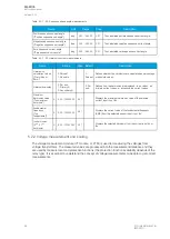
Measurements
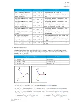
The following measurements are available in the measured voltage channels.
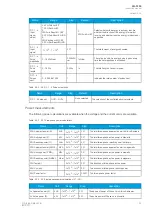
Table. 5.2.2 - 26. Per-unit voltage measurements.
Name
Unit
Range
Step
Description
Voltage Ux
("UxVolt p.u.")
× U
n
0.00…500.0 0.01
The RMS voltage measurement (in p.u.) from each of the voltage channels.
A
AQ
Q-F205
-F205
Instruction manual
Version: 2.04
© Arcteq Relays Ltd
IM00013
75
Содержание AQ F205
Страница 1: ...AQ F205 Feeder protection IED Instruction manual ...
Страница 2: ......
Страница 379: ...Figure 7 4 245 Example block scheme A AQ Q F205 F205 Instruction manual Version 2 04 Arcteq Relays Ltd IM00013 377 ...
Страница 389: ...Figure 8 7 254 Device installation A AQ Q F205 F205 Instruction manual Version 2 04 Arcteq Relays Ltd IM00013 387 ...

