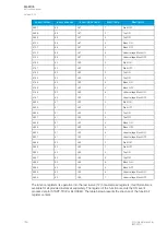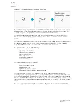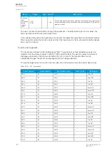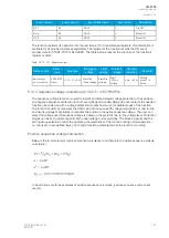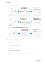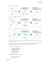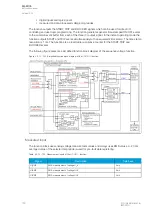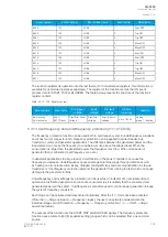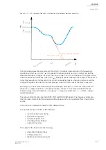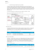
The variables the user can set are binary signals from the system. The blocking signal needs to reach
the device minimum of 5 ms before the set operating delay has passed in order for the blocking to
activate in time.
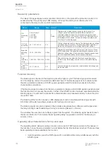
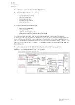
Operating time characteristics for trip and reset
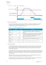
The operating timers’ behavior during a function can be set for TRIP signal and also for the release of
the function in case the pick-up element is reset before the trip time has been reached. There are three
basic operating modes available for the function:
• Instant operation: gives the TRIP signal with no additional time delay simultaneously with the
START signal.
• Definite time operation (DT): gives the TRIP signal after a user-defined time delay regardless
of the measured or calculated voltage as long as the voltage is above the
U
set
value and
thus the pick-up element is active (independent time characteristics).
• Inverse definite minimum time (IDMT): gives the TRIP signal after a time which is in relation
to the set pick-up voltage
U
set
and the measured voltage
U
m
(dependent time
characteristics).
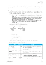
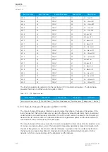
The IDMT function follows one of the following formulas:
Where:
•
t = operating time
•
k = time dial setting
•
U
m
= measured voltage
•
U
s
= pick-up setting
•
a = IDMT multiplier setting
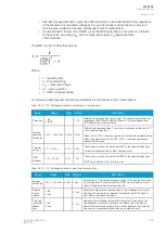
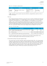
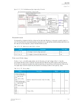
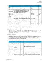
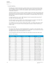
The following table presents the setting parameters for the function's time characteristics.
Table. 5.3.13 - 126. Setting parameters for operating time characteristics.
Name
Range
Step
Default
Description
Delay type 1: DT
2: IDMT
-
1: DT
Selection of the delay type time counter. The selection possibilities are
dependent (IDMT, Inverse Definite Minimum Time) and independent
(DT, Definite Time) characteristics.
Definite
operating
time delay
0.000…1800.000s 0.005s 0.040s
Definite time operating delay. The setting is active and visible when DT
is the selected delay type.
When set to 0.000 s, the stage operates as instant without added delay.
When the parameter is set to 0.005...1800 s, the stage operates as
independent delayed.
Time dial
setting k
0.01…60.00s
0.01s
0.05s
The setting is active and visible when IDMT is the selected delay type.
Time dial/multiplier setting for IDMT characteristics.
IDMT
Multiplier
0.01…25.00s
0.01s
1.00s
The setting is active and visible when IDMT is the selected delay type.
IDMT time multiplier in the U
m
/U
set
power.
A
AQ
Q-F205
-F205
Instruction manual
Version: 2.04
© Arcteq Relays Ltd
IM00013
193
Содержание AQ F205
Страница 1: ...AQ F205 Feeder protection IED Instruction manual ...
Страница 2: ......
Страница 379: ...Figure 7 4 245 Example block scheme A AQ Q F205 F205 Instruction manual Version 2 04 Arcteq Relays Ltd IM00013 377 ...
Страница 389: ...Figure 8 7 254 Device installation A AQ Q F205 F205 Instruction manual Version 2 04 Arcteq Relays Ltd IM00013 387 ...


