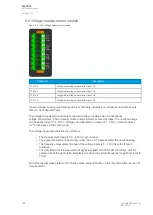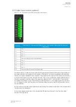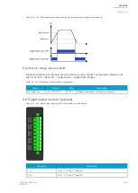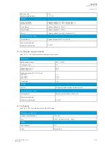
By default, the CPU module (combining the CPU, the I/O and the power supply) includes two standard
communication ports and the relay's basic digital I/O.
The current consumption of the digital inputs is 2 mA when activated, while the range of the operating
voltage is 24 V/110 V/220 V depending on the ordered hardware. All digital inputs are scannced in 5
ms program cycles. Their pick-up and release thresholds depend on the selection of the order code.
Their delays and NO/NC selection, however, can be set with software. The digital output controls are
also set by the user with software. By default, the digital outputs are controlled in 5 ms program cycles.
All output contacts are mechanical. The rated voltage of the NO/NC outputs is 250 VAC/DC.
The auxiliary voltage is defined in the ordering code: the available power supply models available are
A (85…265 VAC/DC) and B (18…75 DC). The power suppy's minimum allowed bridging time for all
voltage levels is above 150 ms. The power supply's maximum power consumption is 15 W. The power
supply allows a DC ripple of below 15 % and the start-up time of the power supply is below 5 ms. For
further details, please refer to the "Auxiliary voltage" chapter in the "Technical data" section of this
document.
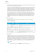
Digital input settings
The settings described in the table below can be found at
Control
→
Device I/O
→
Digital input
settings in the relay settings.
Table. 8.2 - 264. Digital input settings.
Name
Range
Step Default
Description
DIx Polarity
0: NO (Normally
open)
1: NC (Normally
closed)
-
0: NO
Selects whether the status of the digital input is 1 or 0 when the input
is energized.
DIx Activation
delay
0.000…1800.000
s
0.001
s
0.000 s
Defines the delay for the status change from 0 to 1.
DIx Drop-off
time
0.000…1800.000
s
0.001
s
0.000 s
Defines the delay for the status change from 1 to 0.
DIx AC mode
0: Disabled
1: Enabled
-
0:
Disabled
Selects whether or not a 30-ms deactivation delay is added to
account for alternating current.
Scanning cycle
All digital inputs are scanned in a 5 ms cycle, meaning that the state of an input is updated every 0…5
milliseconds. When an input is used internally in the device (either in group change or logic), it takes
additional 0…5 milliseconds to operate. Theoretically, therefore, it takes 0…10 milliseconds to change
the group when a digital input is used for group control or a similar function. In practice, however, the
delay is between 2…8 milliseconds about 95 % of the time. When a digital input is connected directly
to a digital output (T1…Tx), it takes an additional 5 ms round. Therefore, when a digital input controls a
digital output internally, it takes 0…15 milliseconds in theory and 2…13 milliseconds in practice.
NO
NOTE!
TE!
The mechanical delay of the relay is no
nott included in these approximations!
A
AQ
Q-F205
-F205
Instruction manual
Version: 2.04
380
© Arcteq Relays Ltd
IM00013
Содержание AQ F205
Страница 1: ...AQ F205 Feeder protection IED Instruction manual ...
Страница 2: ......
Страница 379: ...Figure 7 4 245 Example block scheme A AQ Q F205 F205 Instruction manual Version 2 04 Arcteq Relays Ltd IM00013 377 ...
Страница 389: ...Figure 8 7 254 Device installation A AQ Q F205 F205 Instruction manual Version 2 04 Arcteq Relays Ltd IM00013 387 ...


