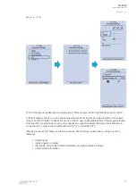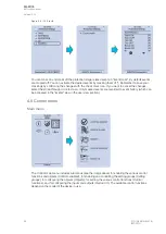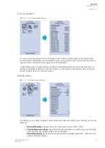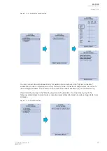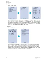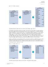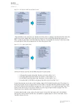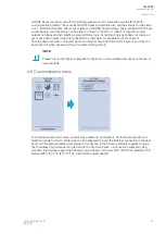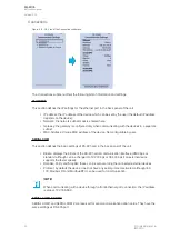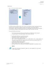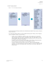
Figure. 4.5 - 34. Device I/O matrix section.
Through the "Device I/O matrix" section you can connect digital inputs, logical outputs, protection stage
status signals (START, TRIP, BLOCKED, etc.), object status signals and many other binary signals to
output relays, or to LEDs configured by the used. A connection can be latched ("|x|") or non-latched
("x"). Please note that a non-latched output is deactivated immediately when the triggering signal is
disabled, while a latched signal stays active until the triggering signal deactivates and the latched
function is manually cleared.
You can clear latched signals by entering the mimic display and the pressing the Back
Back button on the
panel.
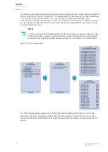
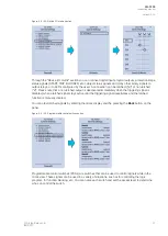
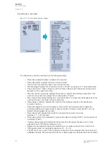
Figure. 4.5 - 35. Programmable control switch section.
Programmable control switches (PCSs) are switches that can be used to control signals while in the
mimic view. These signals can be used in a variety of situations, such as for controlling the logic
program, for function blocking, etc. You can name each switch and set the access level to determine
who can control the switch.
A
AQ
Q-F205
-F205
Instruction manual
Version: 2.04
© Arcteq Relays Ltd
IM00013
37
Содержание AQ F205
Страница 1: ...AQ F205 Feeder protection IED Instruction manual ...
Страница 2: ......
Страница 379: ...Figure 7 4 245 Example block scheme A AQ Q F205 F205 Instruction manual Version 2 04 Arcteq Relays Ltd IM00013 377 ...
Страница 389: ...Figure 8 7 254 Device installation A AQ Q F205 F205 Instruction manual Version 2 04 Arcteq Relays Ltd IM00013 387 ...

