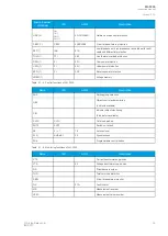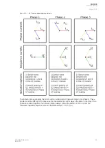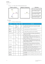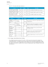
Table. 5.2.1 - 7. Initial data.
PPha
hase curr
se current C
ent CTT
- CT primary: 100 A
- CT secondary: 5 A
R
Ring cor
ing core C
e CT in Input I02
T in Input I02
- I0CT primary: 10 A
- I0CT secondary: 1 A
LLoad (
oad (nominal)
nominal)
36 A
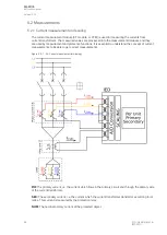
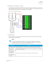
- the phase currents are connected to the I01 residual via a Holmgren connection
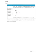
- the starpoint of the phase current CT's secondary current is towards the line
Phase CT scaling
Next, to scale the current to per-unit values, we have to select whether the basis of the phase CT
scaling is the protected object's nominal current or the CT primary value.
If the CT values are chosen to be the basis for the per-unit scaling, the option "CT nom. p.u." is selected
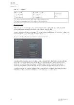
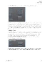
for the "Scale meas to In" setting (see the image below).
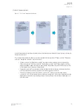
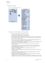
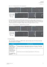
Figure. 5.2.1 - 57. Setting the phase current transformer scalings to CT nominal.
Once the setting have been sent to the device, relay calculates the scaling factors and displays them
for the user. The "CT scaling factor P/S" describes the ratio between the primary current and the
secondary current. The per-unit scaling factors ("Ipu scaling") for both primary and secondary
values are also displayed (in this case they are the set primary and secondary currents of the CT).
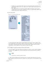
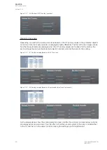
If the protected object's nominal current is chosen to be the basis for the per-unit scaling, the option
"Object in p.u." is selected for the "Scale meas to In" setting (see the image below).
A
AQ
Q-F205
-F205
Instruction manual
Version: 2.04
58
© Arcteq Relays Ltd
IM00013
Содержание AQ F205
Страница 1: ...AQ F205 Feeder protection IED Instruction manual ...
Страница 2: ......
Страница 379: ...Figure 7 4 245 Example block scheme A AQ Q F205 F205 Instruction manual Version 2 04 Arcteq Relays Ltd IM00013 377 ...
Страница 389: ...Figure 8 7 254 Device installation A AQ Q F205 F205 Instruction manual Version 2 04 Arcteq Relays Ltd IM00013 387 ...


