The function constantly monitors the instant values and the key calculated magnitudes of the phase
currents. Additionally, the residual current circuit can be monitored if the residual current is measured
from a dedicated residual current CT. The user can enable and disable the residual circuit monitoring at
will.
The blocking signal and the setting group selection control the operating characteristics of the function
during normal operation, i.e. the user or user-defined logic can change function parameters while the
function is running.
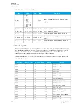
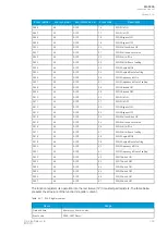
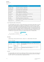
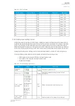
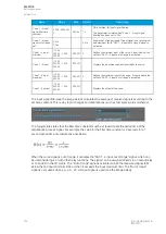
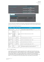
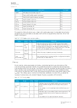
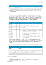
The outputs of the function are the CTS ALARM and BLOCKED signals. The function uses a total of
eight (8) separate setting groups which can be selected from one common source. Also, the operating
mode of the function can be changed via setting group selection.
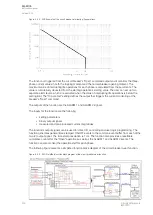
The operational logic consists of the following:
• input magnitude processing
• threshold comparator
• block signal check
• time delay characteristics
• output processing.
The following conditions have to met simultaneously for the function alarm to activate:
• None of the three-phase currents exceeds the
I
set
high limit setting.
• At least one of the three-phase currents exceeds the
I
set
low limit setting.
• At least one of the three-phase currents are below the
I
set
low limit setting.
• The ratio between the calculated minum and maximum of the three-phase currents is below
the
I
set
ratio setting.
• The ratio between the negative sequence and the positive sequence exceeds the
I2/I1
ratio setting.
• The calculated difference (IL1+IL2+IL3+I0) exceeds the
I
sum
difference setting (optional).
• The above-mentioned condition is met until the set time delay for alarm.
The inputs of the function are the following:
• setting parameters
• measured and pre-processed current magnitudes.
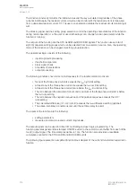
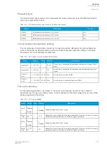
The output signals can be used for direct I/O controlling and user logic programming. The
function generates general time-stamped ON/OFF events to the common event buffer from each of the
two (2) output signal. The time stamp resolution is 1 ms. The function also provides a resettable
cumulative counter for the CTS ALARM and BLOCKED events.
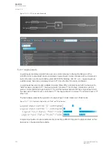
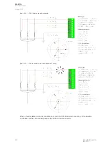
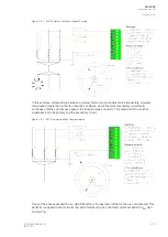
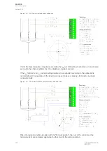
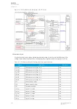
The following figure presents a simplified function block diagram of the current transformer supervision
function.
A
AQ
Q-F205
-F205
Instruction manual
Version: 2.04
316
© Arcteq Relays Ltd
IM00013
Содержание AQ F205
Страница 1: ...AQ F205 Feeder protection IED Instruction manual ...
Страница 2: ......
Страница 379: ...Figure 7 4 245 Example block scheme A AQ Q F205 F205 Instruction manual Version 2 04 Arcteq Relays Ltd IM00013 377 ...
Страница 389: ...Figure 8 7 254 Device installation A AQ Q F205 F205 Instruction manual Version 2 04 Arcteq Relays Ltd IM00013 387 ...


