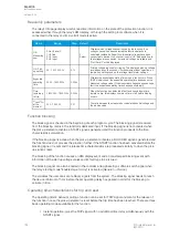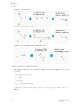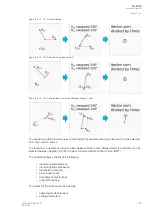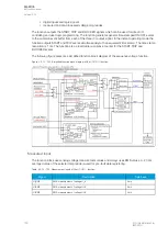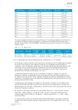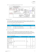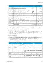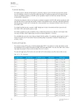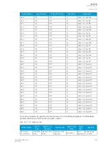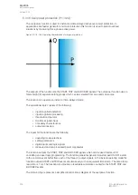
Table. 5.3.13 - 123. Measured magnitude selection.
Name
Description
Range
Default
Measured
magnitude
Selects which calculated voltage is
supervised.
1: U1 Positive sequence
voltage
2: U2 Negative sequence
voltage
1: U1 Positive
sequence voltage
In RMS values the pre-fault condition is presented with 20 ms averaged history value from -20 ms of
START or TRIP event.
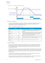
Pick-up
The
U
set
setting parameter controls the pick-up of the U1/U2>/< function. This defines the maximum or
minimum allowed calculated U1 or U2 voltage before action from the function. The function constantly
calculates the ratio between the
U
set
and the calculated U1 or U2 magnitude (
U
c
). The monitored
voltage is chosen in the
Info page with the parameter Measured magnitude. The reset ratio of 97 % in
overvoltage applications is built into the function and is always relative to the
U
set
value. The reset ratio
of 103 % in undervoltage applications is built into the function and is always relative to the
U
set
value.
When the
U
c
goes above or below the
U
set
value it triggers the pick-up operation of the function.
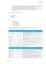
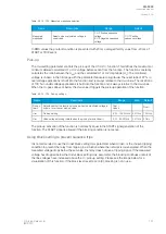
Table. 5.3.13 - 124. Pick-up settings.
Name
Description
Range
Step
Default
Pick-up
terms
Selects whether the function picks-up when the monitored voltage is
under or over the set pick-up value.
Over >
Under<
-
Over>
U
set
Pick-up setting
5.00…150.00%U
n
0.01%U
n
105%U
n
U
blk
Undervoltage blocking (visible when the pick-up term is Under<)
0.00…80.00%U
n
0.01%U
n
5%U
n
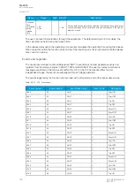
The pick-up activation of the function is not directly equal to the START signal generation of the
function. The START signal is allowed if the blocking condition is not active.
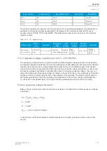
Using
Block setting to prevent nuisance trips
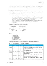
It is recommended to use the
Under block setting U
blk
parameter when Under< is the chosen tripping
condition to prevent the relay from tripping in a situation where the network is de-energized. When the
measured voltage drops below the set value, the relay does not give a tripping signal. If the measured
voltage has dropped below the
Under block setting U
blk
parameter, the blocking continues until all of
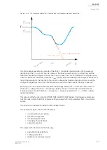
the line voltages have increased above the U< pick-up setting. Please see the image below for a
visualization of this function. If the block level is set to zero (0), blocking is not in use.
A
AQ
Q-F205
-F205
Instruction manual
Version: 2.04
© Arcteq Relays Ltd
IM00013
191
Содержание AQ F205
Страница 1: ...AQ F205 Feeder protection IED Instruction manual ...
Страница 2: ......
Страница 379: ...Figure 7 4 245 Example block scheme A AQ Q F205 F205 Instruction manual Version 2 04 Arcteq Relays Ltd IM00013 377 ...
Страница 389: ...Figure 8 7 254 Device installation A AQ Q F205 F205 Instruction manual Version 2 04 Arcteq Relays Ltd IM00013 387 ...

