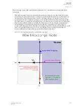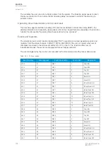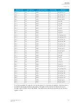
The new broad range mode is capable of detecting an earth fault directionally in both unearthed and
compensated networks not only by combining the two stages together but by using a new multi-criteria
detection. This optional additional tripping condition for compensated networks uses Arcteq’s patented,
high-resolution intermittent earth fault algorithm with added symmetrical component calculation of
phase currents and voltages. If this mode is activated, the alarming criteria is comprised of a measured
residual current in the fourth quadrant and the symmetrical components of voltages and currents
detecting a fault. No extra parameterization is required compared to the traditional method. The multi-
criteria algorithm can be tested with COMTRADE files supplied by Arcteq. The function requires a
connection of three-phase currents, residual current and residual voltage to operate correctly.
To avoid unnecessary alarms the user can add an encroachment area against I0 CT errors in
compensated long healthy lines.
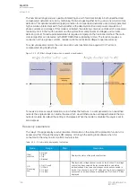
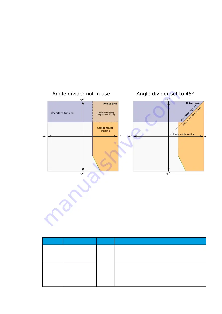
Figure. 5.3.5 - 97. Effect of angle divider when in use and when disabled.
To receive a more accurate indication as to whether the fault was in a compensated or an unearthed
network the angle divider can divide the area which would otherwise be overlapped between the two
network models. By default the setting is 45 degrees. When the divider is disabled the angle is set to
zero degrees.
Read-only parameters
The relay's
Info page displays useful, real-time information on the state of the protection function. It is
accessed either through the relay's HMI display, or through the setting tool software when it is
connected to the relay and its Live Edit mode is active.
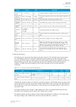
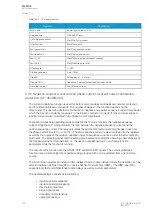
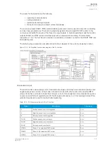
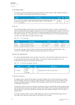
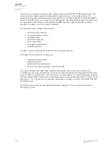
Table. 5.3.5 - 72. Information displayed by the function.
Name
Range
Step
Description
I0dir>
condition
0: Normal
1: Start
2: Trip
3: Blocked
-
Displays the status of the protection function.
U0>
Measuring
now
0: No U0 avail!
1: U0Calc
2: U3 Input
3: U4 Input
-
Displays which voltage channel is used by the function. If no voltage
channel has been selected the function defaults to calculated
residual voltage if line-to-neutral voltages have been connected to
device. If no channel is set to "U0" mode and line-to-line voltages are
connected, no residual voltage is available and "No U0 avail!" will be
displayed.
A
AQ
Q-F205
-F205
Instruction manual
Version: 2.04
126
© Arcteq Relays Ltd
IM00013
Содержание AQ F205
Страница 1: ...AQ F205 Feeder protection IED Instruction manual ...
Страница 2: ......
Страница 379: ...Figure 7 4 245 Example block scheme A AQ Q F205 F205 Instruction manual Version 2 04 Arcteq Relays Ltd IM00013 377 ...
Страница 389: ...Figure 8 7 254 Device installation A AQ Q F205 F205 Instruction manual Version 2 04 Arcteq Relays Ltd IM00013 387 ...

