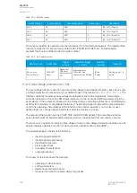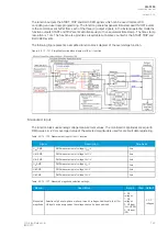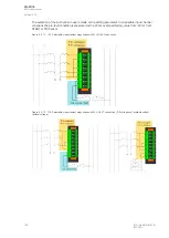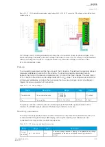
Signal
Description
Time base
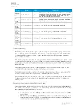
IL2 Ang
Angle of phase L2 (B) current
5ms
IL3 Ang
Angle of phase L3 (C) current
5ms
I01 Ang
Angle of residual input I01
5ms
I02 Ang
Angle of residual input I02
5ms
The selection of the used AI channel is made with a setting parameter.
General settings
The following general settings define the general behavior of the function. These settings are static i.e.
it is not possible to change them by editing the setting group.
Table. 5.3.9 - 95. General settings.
Name
Range Step Default
Description
Restricted earth fault
(REF) or Cable End
Differential
0: REF
1: CED -
0: REF
Selection of the operating characteristics. If REF is selected, the function
operates with normal accuracies. If CED is selected, the natural
unbalance created by the phase current CT:s can be compensated for
more sensitive operation. The default setting is REF.
Compenstate natural
unbalance
0:-
1:
Comp
-
-
When activated while the line is energized, the currently present
calculated residual current is compensated to 0. This compensation only
has an effect in the CED mode.
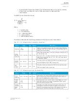
Operating characteristics
The current-dependent pick-up and activation of the function are controlled by setting parameters,
which define the current calculating method used as well as the operating characteristics.
Table. 5.3.9 - 96. Pick-up settings.
Name
Range
Step
Default
Description
I0 Input
0: I01
1: I02
-
0: I01
Selection of the used residual current measurement input.
I0
Direction
0: Add
1: Subtract
-
0: Add
Differential current calculation mode. This matches the directions of the
calculated and measured residual currents to the application. The default
setting (0: Add) means that I01 or I02 in a through
fault yields no differential current.
Bias
current
calculation
0: Residual
current (3I0 +
I0Calc)/2
1: Maximum
(Phase and I0
max)
-
0:
Residual
current
Selection of the bias current calculation. Differential characteristics
biasing can use either the calculated residual current averages or the
maximum of all measured currents. The residual current mode is more
sensitive while the maximum current is coarser.
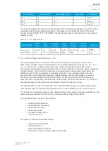
I0d> pick-
up
0.01…50.00%
(of I
n
)
0.01%
10%
Setting for basic sensitivity of the differential characteristics.
Turnpoint
1
0.01…50.00×I
n
0.01×I
n
1.00×I
n
Setting for first turn point in the bias axe of the differential characteristics.
Slope 1
0.01…150.00% 0.01%
10.00%
Setting for the first slope of the differential characteristics.
Turnpoint
2
0.01…50.00×I
n
0.01×I
n
3.00×I
n
Setting for second turn point in the bias axe of the differential
characteristics.
Slope 2
0.01…250.00% 0.01%
40.00%
Setting for the second slope of the differential characteristics.
A
AQ
Q-F205
-F205
Instruction manual
Version: 2.04
© Arcteq Relays Ltd
IM00013
159
Содержание AQ F205
Страница 1: ...AQ F205 Feeder protection IED Instruction manual ...
Страница 2: ......
Страница 379: ...Figure 7 4 245 Example block scheme A AQ Q F205 F205 Instruction manual Version 2 04 Arcteq Relays Ltd IM00013 377 ...
Страница 389: ...Figure 8 7 254 Device installation A AQ Q F205 F205 Instruction manual Version 2 04 Arcteq Relays Ltd IM00013 387 ...


