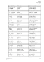
Name
Range
Step Default
Description
Power measurement update
interval
500…10
000ms
5ms
2
000ms
Defines the measurement update interval of all power-related
measurements.
Impedance
measurement update interval
500…10
000ms
5ms
2
000ms
Defines the measurement update interval of all impedance-
related measurements.
6.1.3 Modbus I/O
The Modbus I/O protocol can be selected to communicate on the available serial ports. The Modbus I/
O is actually a Modbus/RTU master implementation that is dedicated to communicating with serial
Modbus/RTU slaves such as RTD input modules. Up to three (3) Modbus/RTU slaves can be
connected to the same bus polled by the Modbus I/O implementation. These are named I/O Module A,
I/O Module B and I/O Module C. Each of the modules can be configured using parameters in the
following two tables.
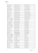
Table. 6.1.3 - 253. Module settings.
Name
Range
Description
I/O module X
address
0…247
Defines the Modbus unit address for the selected I/O Module (A, B, or C). If this setting
is set to "0", the selected module is not in use.
Module x
type
0: ADAM-4018+
1: ADAM-4015
Selects the module type.
Channels in
use
Channel
0…Channel 7 (or
None)
Selects the number of channels to be used by the module.
Table. 6.1.3 - 254. Channel settings.
Name
Range
Step Default
Description
T.C.
type
0: +/- 20mA
1: 4…20mA
2: Type J
3: Type K
4: Type T
5: Type E
6: Type R
7: Type S
-
1:
4…20mA
Selects the thermocouple or the mA input connected to the I/O module.
Types J, K, T and E are nickel-alloy thermocouples, while Types R and S are
platinum/rhodium-alloy thermocouples.
Input
value
-101.0…2
000.0
0.1
-
Displays the input value of the selected channel.
Input
status
0: Invalid
1: OK
-
-
Displays the input status of the selected channel.
6.1.4 IEC 103
IEC 103 is the shortened form of the international standard IEC 60870-5-103. The AQ-200 series units
are able to run as a secondary (slave) station. The IEC 103 protocol can be selected for the serial ports
that are available in the device. A primary (master) station can then communicate with the Arcteq
device and receive information by polling from the slave device. The transfer of disturbance recordings
is not supported.
NO
NOTE
TE: Once the configuration file has been loaded, the IEC 103 map of the relay can be found in the
AQtivate software (
Tools
→
IEC 103 map).
The following table presents the setting parameters for the IEC 103 protocol.
A
AQ
Q-F205
-F205
Instruction manual
Version: 2.04
362
© Arcteq Relays Ltd
IM00013
Содержание AQ F205
Страница 1: ...AQ F205 Feeder protection IED Instruction manual ...
Страница 2: ......
Страница 379: ...Figure 7 4 245 Example block scheme A AQ Q F205 F205 Instruction manual Version 2 04 Arcteq Relays Ltd IM00013 377 ...
Страница 389: ...Figure 8 7 254 Device installation A AQ Q F205 F205 Instruction manual Version 2 04 Arcteq Relays Ltd IM00013 387 ...

