


YASKAWA
TOMPYEULA7002A LA700 Series Installation and Operation Instruction
37
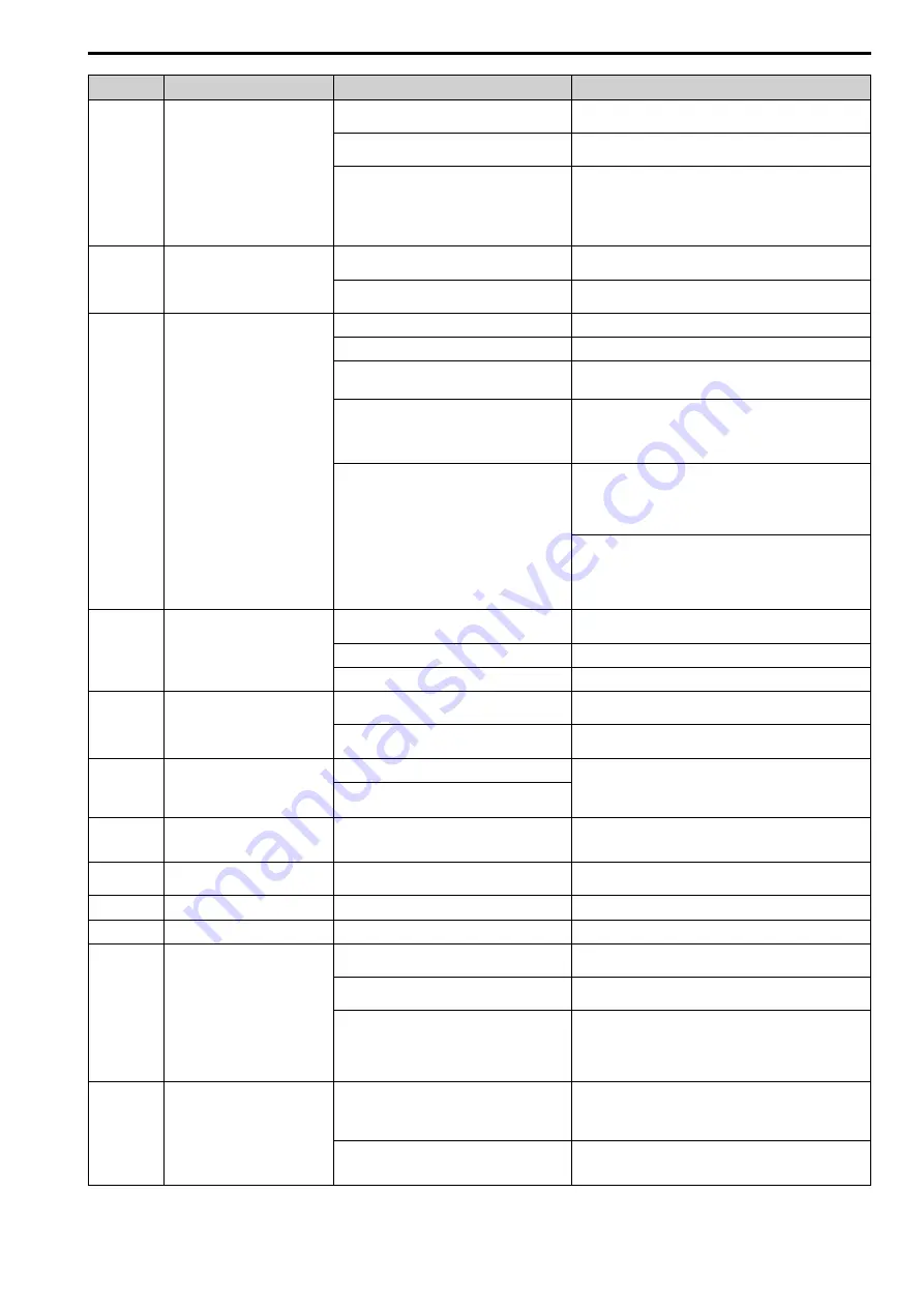
Code
Name
Causes
Possible Solutions
The encoder cable is disconnected or wired
incorrectly.
Examine for wiring errors or disconnected wires in the encoder
cable, and repair problems.
There is motor hunting.
Adjust
n2-02 [Automatic Freq Regulator Time 1]
and
n2-03
[Automatic Freq Regulator Time 2]
.
The drive detects
ov [Overvoltage]
when
A1-02 = 2
[OLV]
and when:
•
The acceleration completes
•
The deceleration starts
•
The load changes suddenly
Increase the value set in
n2-03
in 50 ms increments.
Note:
Make sure that this parameter setting is:
n2-02 ≤ n2-03
.
oS
Overspeed
There is overshoot.
Decrease
C5-01 [ASR Proportional Gain 1]
and increase
C5-02
[ASR Integral Time 1]
.
The
oS
detection level is set incorrectly.
Adjust
F1-08 [Overspeed Detection Level]
and
F1-09 [Overspeed
Detection Delay Time]
.
PF
Input Phase Loss
There is a phase loss in the drive input power.
Correct all wiring errors with the main circuit power supply.
Loose wiring in the input power terminals.
Tighten the screws to the correct tightening torque.
The drive input power voltage is changing too
much.
•
Examine the supply voltage for problems.
•
Make the drive input power stable.
Unsatisfactory balance between voltage phases.
•
Examine the supply voltage for problems.
•
Make the drive input power stable.
•
If the supply voltage is good, examine the magnetic contactor
on the main circuit side for problems.
The main circuit capacitors have become
unserviceable.
•
Examine the capacitor maintenance time in monitor
U4-05
[CapacitorMaintenance]
.
•
If
U4-05
is more than 90%, replace the capacitor. Contact
Yaskawa or your nearest sales representative for more
information.
•
Examine the supply voltage for problems.
•
Re-energize the drive.
•
If the alarm stays, replace the circuit board or the drive.
Contact Yaskawa or your nearest sales representative for more
information.
PGo
Encoder (PG) Feedback Loss
The encoder cable is disconnected or wired
incorrectly.
Examine for wiring errors or disconnected wires in the encoder
cable, and repair problems.
The encoder is not receiving power.
Examine the encoder power supply.
The holding brake is stopping the motor.
Release the holding brake.
rF
Braking Resistor Fault
The resistance of the dynamic braking option that is
connected to the drive is too low.
Use a dynamic braking option that fits the model and duty rating
of the drive.
A regenerative converter, regenerative unit, or
braking unit is connected to the drive.
Set
L8-55 = 0 [Internal DB TransistorProtection = Disable]
.
rr
Dynamic Braking Transistor Fault
The drive control circuit is damaged.
There is a malfunction in the internal braking
transistor of the drive.
•
Re-energize the drive.
•
If the fault stays, replace the control board or the drive. For
information about replacing the control board, contact
Yaskawa or your nearest sales representative.
SCF
Safety Circuit Fault
The safety circuit is broken.
Replace the control board or the drive. For information about
replacing the control board, contact Yaskawa or your nearest sales
representative.
SE1
Motor Contactor Response Error
There is a problem with the motor contactor or
auxiliary switch.
Examine the motor contactor, auxiliary switches, and the wiring
of the contactor feedback signal.
SE2
Starting Current Error
The motor contactor is open.
Check the contactor for any problems.
SE3
Output Current Error
The motor contactor is open.
Check the contactor for any problems.
SE4
Brake Response Error
The feedback contact on the brake is defective or
the wiring is incorrect.
Check the brake feedback contact and the wiring.
The brake control circuit does not work correctly.
Make sure that the motor brake operates correctly with a brake
control command from the drive.
The motor contactor or relay for the brake is open.
•
Check the contactor for any problems.
•
When
S6-07 = 1 [Brake Response Monitor Function =
Enabled]
, check the motor contactor or relay. When there are
no problems, set
S6-08 = 1 [SE4 Fault Reset = Enabled]
to
reset the fault.
STo
Safe Torque OFF
Safe Disable inputs H1-HC and H2-HC are open.
•
Make sure that the Safe Disable signal is input from an
external source to terminal H1-HC and H2-HC.
•
When the Safe Disable function is not in use, connect
terminals H1-HC and H2-HC.
There is internal damage to the two Safe Disable
channels.
Replace the board or the drive. For information about replacing
the control board, contact Yaskawa or your nearest sales
representative.