


26
YASKAWA
TOMPYEULA7002A LA700 Series Installation and Operation Instruction
•
The motor rotates in a different direction than expected.
To use the Rotation Direction Trouble Shoot function, select [Menu] > [Diagnostic Tools] > [Rotation Direction
Trouble Shoot] from the HOME screen. Select a problem to solve and [Execute trouble shoot], then push
.
Refer to the Technical Manual for more information about this function.
■
Setting the Encoder (Pulse Generator)
Encoder Resolution Setup
Set the encoder resolution (incremental signal in case of absolute encoders with Sin/Cos tracks) in
F1-01
[Encoder 1 Pulse Count (PPR)]
.
Encoder Rotation Direction Setup
Do these steps to make sure that the encoder rotation direction is set up correctly in the drive.
•
When information about the signal sequence of the encoder is available:
–
Check the sequence of encoder phases A and B when the motor drives the elevator in the Up direction.
–
If the encoder A phase leads phase B, set
F1-05 = 0 [Encoder 1 Rotation Selection = Pulse A leads in Up
Direction]
.
–
If the encoder B phase leads phase A, set
F1-05 = 1 [Pulse B leads in Up Direction]
.
•
When information about the signal sequence of the encoder is not available:
–
Manually turn the motor in the elevator Up direction while you check the value of
U1-05 [Speed Feedback]
.
–
If the value in
U1-05
is positive, the encoder direction is correct.
–
If the value in
U1-05
is negative, change the setting of
F1-05
.
Note:
Always do the motor rotation direction setup before you set the encoder rotation direction. Refer to
Setting the Motor Rotation Direction
.
■
Keypad Display Unit Selection
You can use
o1-03 [Speed Display Unit Selection]
to choose between different display units for speed-related
parameters and monitors, acceleration and deceleration ramps, and jerk characteristics. Use the table below to
determine the correct
o1-03
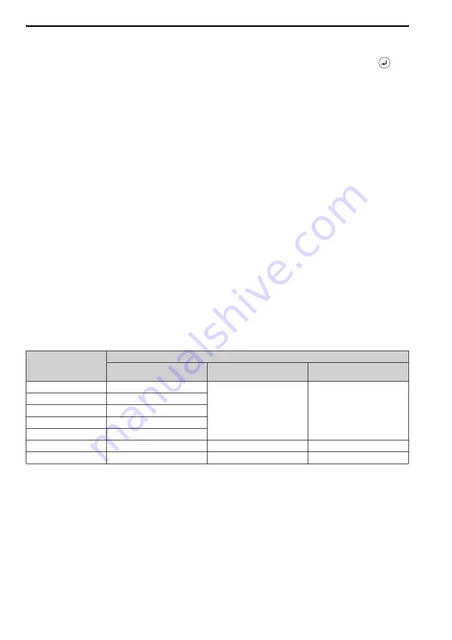
setting for your application.
o1-03 Setting
Display Unit
Speed Reference Settings/Monitors
(d1-xx, U1-01, U1-02,...)
Accel & Decel Ramp
(C1-xx)
Jerk Characteristics
(C2-xx)
0 [0.01 Hz]
0.01 Hz
0.01 s
0.01 s
1 [0.01% (100% = E1-04)]
0.01%
2 [Revolutions Per Minute (RPM)]
1 rpm
3 [User Units (o1-10 & o1-11)]
User defined
4 [Elevator Unit1 - m/s, s, s]
0.01 m/s
5 [Elevator Unit2 - m/(s, s^2, s^3)]
0.01 m/s
0.01 m/s
2
0.01 m/s
3
6 [Elevator Unit3-ft/(min,s^2,s^3)]
0.1 ft/min
0.01 ft/s
2
0.01 ft/s
3
If you want to use settings 4 to 6, you must program certain mechanical data to the drive before you change
o1-03
.
1. Correctly set the motor data. Make sure that the settings for
E1-04 [Maximum Output Frequency]
and
E2-04
[Motor Pole Count]
or
E5-04 [PM Motor Pole Count]
are correct.
2. Set up the elevator mechanics:
a.
Use dedicated mechanical data:
i.
Set the traction sheave diameter in mm units to
o1-20 [Sheave Diameter]
.
ii.
Set the correct roping to
o1-21 [Roping Ratio]
.
iii.
When you use a geared machine, set the gear ratio (n
Motor
/n
Traction Sheave
) to
o1-22 [Mechanical
Gear Ratio]
. When you use a gearless machine, set
o1-22 = 1.0
.
iv.
Set
o1-03 = 4, 5, or 6
. The drive will automatically change the unit and setting values of related
parameters.