WAGO-I/O-SYSTEM 750
I/O Modules 169
750-806 Fieldbus Controller DeviceNet
TM
Manual
Version 2.0.0
12.2
Process Data Architecture for DeviceNet
TM
For some I/O modules (and their variants), the architecture of the process data
depends on the fieldbus.
With the DeviceNet
TM
fieldbus controller, the process image uses a byte structure
(no word alignment). The internal mapping method for data greater than one byte
conforms to Intel formats.
The fieldbus-specific representation of compatible I/O modules in the process
image of the DeviceNet
TM
fieldbus controller is described based on examples.
Take into account the process data of all connected I/O modules!
Depending on the specific position of an I/O module in the fieldbus node, the
process data of all previous byte- or bit-oriented modules must be taken into
account to determine its location in the process data map.
12.2.1
Digital Input Modules
The digital input modules provide a process value of one bit per channel, which
indicates the status of the respective channel. These bits are mapped in the input
process image.
Each input channel occupies one instance in the “Discrete Input Point Object”
(Class 0x65). I/O modules with data bits assigned by channel also occupy more
instances of this class accordingly.
Example: 2-channel digital input modules with diagnostics (4 instances)
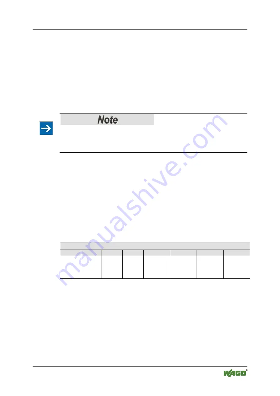
Table 120: 2-Channel Digital Input Modules with Diagnostics (4 Instances)
Input Process Image
Bit 7
Bit 6
Bit 5
Bit 4
Bit 3
Bit 2
Bit 1
Bit 0
Diagnostic
bit
S 2
Channel 2
Diagnostic
bit S 1
Channel 1
Data bit
DI 2
Channel 2
Data bit
DI 1
Channel 1
These input modules occupy 4 instances in the “Discrete Input Point Object”
(0x65) class.
Some digital input modules provide additional data, e.g., acknowledgements
mapped in the output process image. The output data of these I/O modules
occupies a corresponding number of instances in class (0x66).


