


2-16
1020NFM-1D
Section 2
2.7.2 ESTABLISHING COMMUNICATIONS USING HyperTerminal
This section shows how to communicate with 1020 using the Windows based communication pro-
gram HyperTerminal. It assumes that you’re familiar with Windows 95/98/NT/2000/XP and have a
basic understanding of serial communications.
All IBM compatible computers provide at least one serial port using a 9-pin connector. The port desig-
nation can be either COM 1 or COM 2. Usually, when a computer has two serial ports, COM 1 will be
the 9-pin connector and COM 2 will be the 25-pin connector. However, port designations can vary from
manufacturer to manufacturer, so you will have to positively identify the COM port you wish to use for
the flow computer interface. Connect cable between the flow computer and your PC using the 9-pin
connector.
NOTE: Be aware that on some laptop computers, the available COM ports may be assigned to
peripheral devices, such as a modem, mouse or an infrared port, etc. Therefore, you
may not have a COM port available for this interface. In such a case, refer to your PC
manual for instructions on how to reassign your COM ports for standard operation.
The following example explains how to set up HyperTerminal:
z
From the Windows 95/98/NT/2000/XP desktop, Left-Click on the [START] button.
z
Holding down the left mouse button, move the highlight up to [Programs], then across to [Accesso-
ries]. Slide the highlight down to [HyperTerminal], then release the left mouse button.
z
Within the HyperTerminal window, move the mouse pointer down to [Hyperterm.exe] and then
double-click the left mouse button.
z
This selects the [Connection Description] dialog box. Enter a name for your connection (e.g., 1020N).
You can optionally select an icon for this connection by clicking on one of the icons displayed in the
scrolling frame at the bottom of the window. Click [OK].
z
This selects the [Phone Number] dialog box. Move cursor to the arrow at right of [Connect Using]
field. Left click on arrow to expand field and move the highlight down to [Direct to Com 1 (or 2)]
depending on the port connected to the interface cable. Click [OK] to select [Com 1 (or 2) Proper-
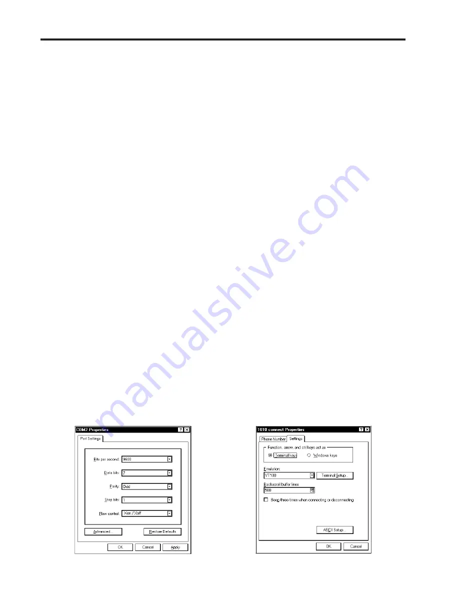
ties] Dialog box. Set up your RS-232 parameters as shown (below left). Left-click on the [OK]
button.
z
You will now see a blank terminal screen. Next click [File] on the top menu bar. Drag the highlight
down to [Properties] and then left-click.
z
Left-click [Settings] tab. Expand the [Emulation] box by clicking the <Down Arrow> on the right-
hand side. Drag the highlight down to [VT-100] and then left-click to select it as shown (below right).
Summary of Contents for SITRANS FUS1020
Page 3: ......
Page 206: ......
Page 207: ......
Page 208: ......
Page 209: ......
Page 210: ......
Page 211: ......
Page 212: ......
Page 213: ......
Page 214: ......
Page 215: ......
Page 216: ......
Page 217: ......
Page 218: ......
Page 219: ......
Page 220: ......
Page 221: ...21614 C ...
Page 222: ...21614 C ...
Page 223: ...990TNHM 8 OUTLINE DIMENSIONS TRANSDUCERS TRACKS DEDICATED HYBRID MODE 21614 C ...
Page 224: ...1011FTP 8 21614 C ...
Page 225: ...1011FTNF 8 21614 C ...
Page 226: ...21614 C PFA DFT FLOWTUBE INSTALLATION OUTLINE 992DFTP T 8 ...
Page 227: ...INSTALLATION OUTLINE 992 SERIES EXTENDED FLOWTUBE 21614 C 992DFTN 8 ...
Page 228: ......