


6-6
1020NFM-1D
Section 6
You may select up to eight characters. If you decide to use numbers or a decimal point in the site
name, you can also type these characters directly from your PC keyboard.
To Save or Rename a Site Setup:
Type the site name with the PC keyboard or use the KeyPad and pressthe <Right Arrow> to
access the first character position.
To select a character press the <Up/Down Arrows> then <ENTER> to highlight to next charac-
ter position.
To select the second character press the <Up/Down Arrows>. Repeat this process to select
all the characters (8 max.).
To save the site data present in Active Memory press <ENTER>.
6.2
THE PIPE DATA MENU
This menu becomes available after picking a Meter Type, Measurement Channel and Measurement
Technology. We recommend that you edit the Pipe Data immediately after creating a new Site Setup.
The Pipe Data menu allows you to define the application’s pipe parameters. Select a pipe from one of
the meter’s stored pipe tables (see menu structure below); or input the pipe size and description
manually. Manual entries include Pipe Material, Outer Diameter (OD) and pipe Wall Thickness. Liner
Material and Liner Thickness entries are included to support pipes with liners. The meter requires the
pipe outer diameter (OD) and wall thickness to operate. You must define these parameters to com-
plete the installation.
The pipe table includes descriptions for over sixty standard pipes plus any user-entered pipes (see
Meter Facilities). To use these presets, first pick a Pipe Class (e.g., ASA Stainless Steel), then pick a
pipe size within that class (e.g., 4SS10). When you select a particular pipe class/size, the relevant
pipe parameters appear in the [Pipe Data] menu cells. If a given pipe class/size does not match your
application exactly you can still edit each individual parameter to fine-tune your selection. In addition,
the Meter Facilities section of the Installation Menu provides a pipe table editor that allows you to
customize any or all of the stored pipe tables.
NOTE: If you edit the pipe parameters after the system is operating, you will have to repeat
the transducer install procedure.
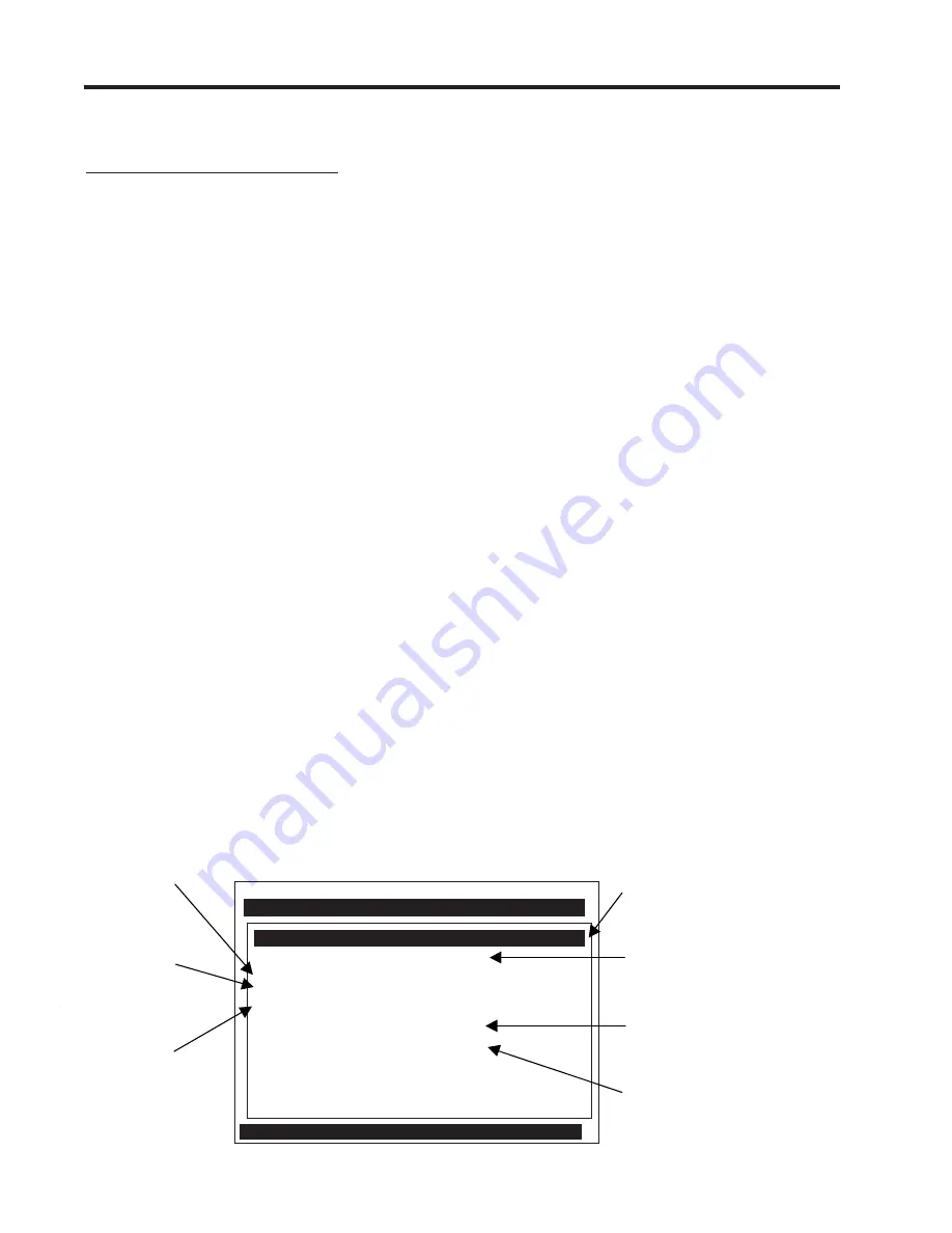
Siemens 2 Channel [1]
ABC
Select Pipe Class from Pipe Table
Select Pipe Size
No Pipes
Pipe OD <in>
0.500
Pipe Material
Steel
Wall Thickness
0.100
Liner Material
None
Liner Thickness
0.000
Select Pipe Class
Manual Entry
Pipe Data
Use this menu
cell to edit the
wall thickness.
Use this menu
cell to edit the
pipe material.
Use this menu
cell to edit the
pipe outer
diameter.
Use this menu cell to edit
the pipe liner thickness.
Use this menu cell to
select a pipe liner
material.
After picking a pipe class,
use this menu cell to
select a pipe from within
that class.
Use this menu cell to select a Pipe
Class from one of the meter's presets.
The [Manual Entry] selection (default)
means that you enter pipe data
manually.
Summary of Contents for SITRANS FUS1020
Page 3: ......
Page 206: ......
Page 207: ......
Page 208: ......
Page 209: ......
Page 210: ......
Page 211: ......
Page 212: ......
Page 213: ......
Page 214: ......
Page 215: ......
Page 216: ......
Page 217: ......
Page 218: ......
Page 219: ......
Page 220: ......
Page 221: ...21614 C ...
Page 222: ...21614 C ...
Page 223: ...990TNHM 8 OUTLINE DIMENSIONS TRANSDUCERS TRACKS DEDICATED HYBRID MODE 21614 C ...
Page 224: ...1011FTP 8 21614 C ...
Page 225: ...1011FTNF 8 21614 C ...
Page 226: ...21614 C PFA DFT FLOWTUBE INSTALLATION OUTLINE 992DFTP T 8 ...
Page 227: ...INSTALLATION OUTLINE 992 SERIES EXTENDED FLOWTUBE 21614 C 992DFTN 8 ...
Page 228: ......