


2-6
1020NFM-1D
Section 2
2.5
CHOOSING A PROGRAMMING INTERFACE
As mentioned previously, site setup is accomplished under the control of an Installation Menu that
allows you to enter information that is specific to each site. System 1020 provides two ways of access-
ing the Installation Menu. You can view the Installation Menu locally on the 16 x 2 character LCD panel
display and use the 5-key Touch KeyPad
for navigation and data entry. Alternately, you can access the
Installation Menu using a personal computer connected to the instrument via its RS-232 compatible
serial port.
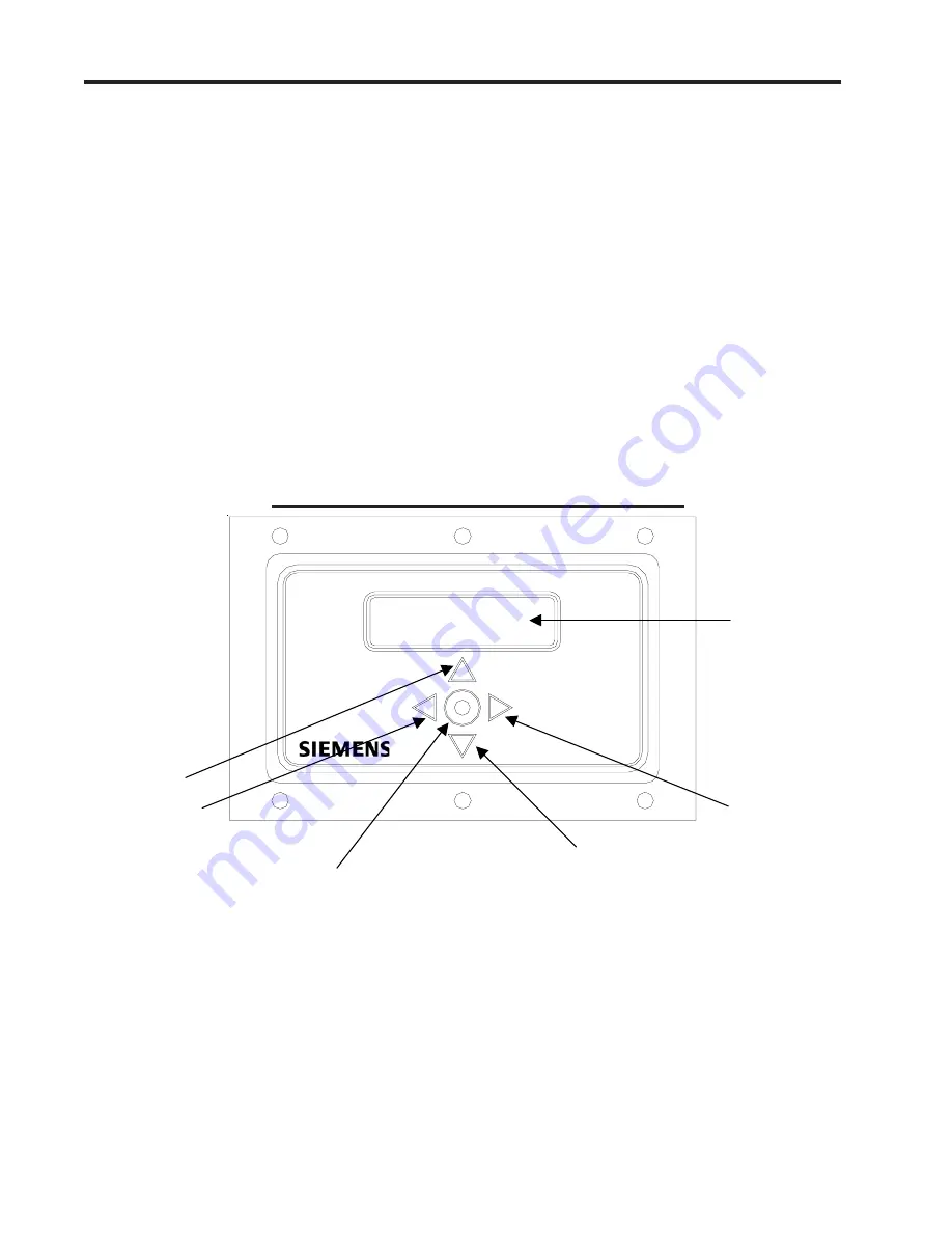
2.5.1 OVERVIEW OF THE 5-KEY TOUCH KEYPAD
The KeyPad interface provides a simple data entry method that is viewed via the 2x16 integral LCD
display. It is not necessary to open the housing to effect data entry, thus avoiding the need for hot-work
permits and the like for user menu access.
Individual functions and parameters are selected from a hierarchical menu structure. Menu control and
navigation is accomplished by simply pressing the keys on the KeyPad. The Touch KeyPad provides
five keys. Four of the keys are used for directional navigation within the Installation Menu. A symbol on
each key shows the effective direction. The fifth key provides the ENTER function (bullseye).
2.5.2 OVERVIEW OF THE RS-232 INTERFACE
System 1020 site parameters can also be programmed using a PC connected to the RS-232 serial
port. This requires a standard DB-9 serial cable connector and a communication software package.
The serial interface jack (J1) is a 9-pin connector that accommodates IBM-compatible serial ports. A
PC communication program such as Terminal (Windows 3.x) or HyperTerminal (Windows 95/98/NT/
2000/XP) serves as the interface. These programs reproduce the menu screens that appear on 1010/
1020 systems equipped with graphic display screens. Setup procedures for the 1020 and portable
units, or dedicated graphic screen displays, are identical. We recommend this method because it
allows you to view the Installation Menu using a 40 character by 12-line interface. The following ex-
ample screen is an actual HyperTerminal screen capture.
SYSTEM 1020 LCD DISPLAY PANEL AND KEYPAD
Wide Beam
Clamp-On
Ultrasonic
Flowmeter
UP KEY
LEFT KEY
ENTER KEY
DOWN KEY
RIGHT KEY
2-LINE LCD
DISPLAY
Siemens1020
Copyright 2006
Wide Beam
Clamp-On
Ultrasonic
Flowmeter
Summary of Contents for SITRANS FUS1020
Page 3: ......
Page 206: ......
Page 207: ......
Page 208: ......
Page 209: ......
Page 210: ......
Page 211: ......
Page 212: ......
Page 213: ......
Page 214: ......
Page 215: ......
Page 216: ......
Page 217: ......
Page 218: ......
Page 219: ......
Page 220: ......
Page 221: ...21614 C ...
Page 222: ...21614 C ...
Page 223: ...990TNHM 8 OUTLINE DIMENSIONS TRANSDUCERS TRACKS DEDICATED HYBRID MODE 21614 C ...
Page 224: ...1011FTP 8 21614 C ...
Page 225: ...1011FTNF 8 21614 C ...
Page 226: ...21614 C PFA DFT FLOWTUBE INSTALLATION OUTLINE 992DFTP T 8 ...
Page 227: ...INSTALLATION OUTLINE 992 SERIES EXTENDED FLOWTUBE 21614 C 992DFTN 8 ...
Page 228: ......