Operating
7.12 Open Channel Monitoring (OCM)
HydroRanger 200 HMI
Operating Instructions, 06/2018, A5E36281317-AC
143
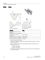
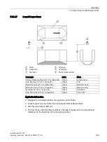
7.12.4.3
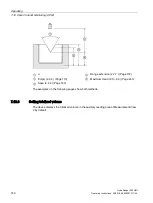
Palmer-Bowlus flume
①
Flow
⑤
Upper scaling point
②
Transducer
1)
⑥
Zero head (2.13.4.5.) (Page 244)
③
Empty (2.2.4.) (Page 170)
⑦
D = pipe or sewer diameter
④
Span (2.2.2.) (Page 169)
⑧
D/2, point of measurement
2)
Parameter
Mode
Primary Measuring Device (2.13.2.)
(Page 240)
Palmer-Bowlus
PMD Dimensions (2.13.5.) (Page 246)
(Page 246)
Flume width (D)
Maximum Head (2.13.4.2.) (Page 243)
Maximum Head
Maximum Flow (2.13.4.3.) (Page 243)
Maximum Flow
Zero Head (2.13.4.5.) (Page 244)
Zero Head
Flow Time Units (2.13.4.4.) (Page 244) Time Units
Application information
●
Sized by pipe diameter D
●
Flume relief is trapezoidal
●
Designed to install directly into pipelines and manholes
●
Head is referenced to bottom of the throat, not bottom of the pipe
●
For rated flows under free flow conditions, the head is measured at a distance of D/2
upstream from the beginning of the converging section.
Summary of Contents for HydroRanger 200 HMI
Page 2: ......
Page 24: ...Safety notes HydroRanger 200 HMI 22 Operating Instructions 06 2018 A5E36281317 AC ...
Page 354: ...Updating software HydroRanger 200 HMI 352 Operating Instructions 06 2018 A5E36281317 AC ...
Page 362: ......
Page 403: ......


