Parameter reference
8.3 Index selector examples
HydroRanger 200 HMI
Operating Instructions, 06/2018, A5E36281317-AC
159
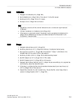
8.3.2
Calibration
1.
Navigate to Calibration (2.2.) (Page 169).
2.
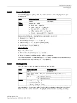
Set Calibration (2.2.) (Page 169) to Transducer 1 for the first vessel.
3.
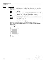
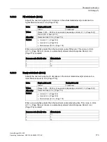
Set Empty (2.2.4.) (Page 170) to 2.5 meters.
4.
Set Span (2.2.2.) (Page 169) to 2 meters.
Note
•
Repeat this procedure for the second ultrasonic sensor or when mA input has been
configured.
•
Choose Transducer 2 in Calibration (2.2.) (Page 169).
•
If the device is a dual-point model, Transducer 3 will be available in Calibration (2.2.)
(Page 169) for Differential or Average calculations between the Transducer 1 and
Transducer 2 measurements.
8.3.3
Pumps
1.
Navigate to Basic Setup (2.8.1.) (Page 193)
2.
Set Relay Selector (2.8.1.1.) (Page 195) to Relay 1 to program the first pump.
3.
Set Level Source (2.8.1.2.) (Page 194) to Transducer 1. Relay 1 will activate or de-
activate based on the values of this measurement.
4.
Set Relay Function (2.8.1.4.) (Page 195) to Alternate Duty Assist.
5.
Set ON Setpoint. (2.8.1.5.) (Page 197) to 1.25 meters.
6.
Set OFF Setpoint (2.8.1.6.) (Page 197) to 0.25 meters.
7.
Navigate back to Relay Selector (2.8.1.1.) (Page 193) and select Relay 2 to program the
second pump, using new setpoint values.
8.
If the relay is controlled by the second transducer measurement, set Level Source (2
2.8.1.2.) (Page 194) to Transducer 2.
9.
Repeat this procedure for each required relay. Ensure that the correct relay index is
selected in Relay Selector (2.8.1.1.) (Page 195).
Summary of Contents for HydroRanger 200 HMI
Page 2: ......
Page 24: ...Safety notes HydroRanger 200 HMI 22 Operating Instructions 06 2018 A5E36281317 AC ...
Page 354: ...Updating software HydroRanger 200 HMI 352 Operating Instructions 06 2018 A5E36281317 AC ...
Page 362: ......
Page 403: ......

