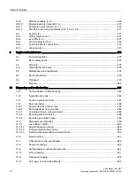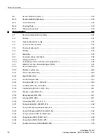
Table of contents
HydroRanger 200 HMI
6
Operating Instructions, 06/2018, A5E36281317-AC
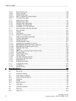
7.9.4.7
Reducing wall cling .............................................................................................................. 129
7.9.4.8
Grouping pumps................................................................................................................... 130
7.9.4.9
Setting a flush valve ............................................................................................................. 130
7.9.4.10
Relay controlled by communications ................................................................................... 131
7.9.4.11
Tracking pump usage .......................................................................................................... 131
7.10
Rake (screen) control ........................................................................................................... 131
7.10.1
Setting a rake control ........................................................................................................... 132
7.10.2
Setting common parameters ................................................................................................ 133
7.10.3
Set Relay 1 (Operate Rake) ................................................................................................. 133
7.10.4
Set Relays 2 to 4 (Level Alarms) ......................................................................................... 134
7.11
External totalizers and flow samplers .................................................................................. 134
7.11.1
Relay contacts ...................................................................................................................... 135
7.11.2
Totalizer ............................................................................................................................... 135
7.11.3
Flow sampler ........................................................................................................................ 136
7.11.3.1
Based on volume and time .................................................................................................. 136
7.12
Open Channel Monitoring (OCM) ........................................................................................ 137
7.12.1
Common parameters ........................................................................................................... 138
7.12.2
Setting Zero Head ................................................................................................................ 139
7.12.3
Setting totalized volume ....................................................................................................... 140
7.12.4
Applications supported by the device .................................................................................. 141
7.12.4.1
BS-3680/ISO 1438/1 Thin Plate V-notch weir ..................................................................... 141
7.12.4.2
BS-3680/ISO 4359 Rectangular Flume ............................................................................... 142
7.12.4.3
Palmer-Bowlus flume ........................................................................................................... 143
7.12.4.4
H-flume ................................................................................................................................. 144
7.12.4.5
PMDs with exponential flow to Head Function .................................................................... 145
7.12.4.6
Parshall Flume ..................................................................................................................... 148
7.12.4.7
Leopold-Lagco flume ........................................................................................................... 149
7.12.4.8
Cut throat flume.................................................................................................................... 150
7.12.5
Universal calculation support ............................................................................................... 151
7.12.6
Typical flow characterization ................................................................................................ 151
7.12.7
Example flumes.................................................................................................................... 152
7.12.8
Example weir profiles ........................................................................................................... 153
7.13
Configuration testing ............................................................................................................ 153
7.13.1
I/0 Checkout ......................................................................................................................... 153
7.13.2
Application test ..................................................................................................................... 154
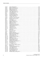
8
Parameter reference .............................................................................................................................. 155
8.1
Key terms ............................................................................................................................. 155
8.2
Parameter indexing .............................................................................................................. 156
8.3
Index selector examples ...................................................................................................... 158
8.3.1
Sensor and measurement .................................................................................................... 158
8.3.2
Calibration ............................................................................................................................ 159
8.3.3
Pumps .................................................................................................................................. 159
8.3.4
High level alarm ................................................................................................................... 160
8.4
Index types ........................................................................................................................... 161
8.5
Quick Start Wizards ............................................................................................................. 162
8.6
Setup (2.) ............................................................................................................................. 162
8.6.1
Sensor (2.1.) ........................................................................................................................ 162
Summary of Contents for HydroRanger 200 HMI
Page 2: ......
Page 24: ...Safety notes HydroRanger 200 HMI 22 Operating Instructions 06 2018 A5E36281317 AC ...
Page 354: ...Updating software HydroRanger 200 HMI 352 Operating Instructions 06 2018 A5E36281317 AC ...
Page 362: ......
Page 403: ......


