background image

Menu item

Description

Options

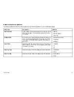
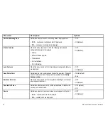
Record Vessel Track By

Determines how track points are recorded on the chart:

Auto

— track points are automatically created.

Time

— track points are created based on time.

Distance

— track points are created based on distance.

• Auto (default)

• Time

• Distance

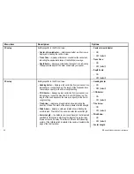
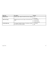
Track Interval

Determines the interval that will be used for track point creation. The
options available depend on the option selected for the

Record Vessel

Track By

menu item, as follows:

Auto

— if the Auto option is selected for the

Record Vessel Track

By

menu item, no options are available for the

Track Interval

menu

item.

Time

— if the Time option is selected for the

Record Vessel Track

By

menu item, you can use the

Track Interval

menu item to specify

the time interval.

Distance

— if the Distance option is selected for the

Record Vessel

Track By

menu item, you can use the

Track Interval

menu item to

specify the distance interval. The units used for this setting depend
on the setting made for

Distance Units

in the

MENU > System

Setup > Units Setup

menu.

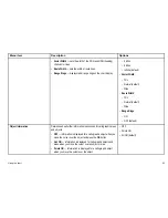
If TIME is selected for the

Record Vessel Track

By

menu item:

• 2 secs

• 5 secs

• 10 secs

• 30 secs

• 1 min

• 3 min

• 5 min

• 10 min

• 30 min

If DISTANCE is selected for the

Record Vessel

Track By

menu item:

• 0.02 nm / sm / km

• 0.05 nm / sm / km

• 0.1 nm / sm / km

• 0.2 nm / sm / km

• 0.5 nm / sm / km

94

E-Series Widescreen User reference

Summary of Contents for E90W

Page 1: ...E Series Widescreen Multifunction Display User reference handbook E90W E120W and E140W models E Series Widescreen User reference...

Page 2: ......

Page 3: ...star ST40 ST60 Seaclutter Smart Route Tridata UniControl Hybridtouch and Waypoint Navigation are trademarks of Raymarine UK Limited All other product names are trademarks or registered trademarks of t...

Page 4: ......

Page 5: ...Display power 20 3 3 Controls 21 3 4 Hybridtouch overview 23 3 5 Touchscreen overview 24 3 6 Home screen overview 24 3 7 Pages 25 3 8 Applications 27 3 9 Screen overview 29 3 10 Editing information i...

Page 6: ...Using radar 115 9 1 Radar overview 116 9 2 HD and SuperHD digital radar scan speed 116 9 3 Radar scanner status symbols 117 9 4 Radar range and image quality 118 9 5 Radar display overview 121 9 6 Du...

Page 7: ...g the engine panel dial color 189 13 5 Pre configured data panels 190 13 6 Changing what the engine application displays 192 Chapter 14 Using the data application 193 14 1 Data application overview 19...

Page 8: ...your display 226 19 2 Enabling DSC VHF radio integration 227 Chapter 20 Customizing your display 229 20 1 Customizing the vessel icon 230 20 2 Customizing the databar 231 20 3 System setup menu 232 Ch...

Page 9: ...at and or poor product performance Warning High voltages This product contains high voltages Do NOT remove any covers or otherwise attempt to access internal components unless specifically instructed...

Page 10: ...istor TFT LCD units the screen may exhibit a few less than 7 wrongly illuminated pixels These may appear as black pixels in a light area of the screen or as colored pixels in black areas Water ingress...

Page 11: ...ine recommends the use of quality branded CF memory cards Some brands of CF memory card may not work in your unit Please contact customer support for a list of recommended CF cards EMC conformance Ray...

Page 12: ...that you register your product to receive full warranty benefits Your unit package includes a bar code label indicating the serial number of the unit You should stick this label to the warranty regist...

Page 13: ...Chapter 2 Handbook information Chapter contents 2 1 Handbook information on page 14 2 2 Handbook conventions on page 15 Handbook information 13...

Page 14: ...al equipment to be operated with it is compatible and has been correctly installed This handbook is intended for users of varying marine abilities but assumes a general level of knowledge of display u...

Page 15: ...the term select is used in procedures involving softkeys to refer to the action of selecting a softkey either using touch or by pressing the corresponding physical key Menus the term select is used in...

Page 16: ...16 E Series Widescreen User reference...

Page 17: ...dtouch overview on page 23 3 5 Touchscreen overview on page 24 3 6 Home screen overview on page 24 3 7 Pages on page 25 3 8 Applications on page 27 3 9 Screen overview on page 29 3 10 Editing informat...

Page 18: ...er Fishfinder DSM 30 300 or 400 SeaTalkhs switch Instruments Autopilot AIS receiver DSC VHF E Series display Additional E Series display s Video Camera D11692_1 Digital Open Array radar scanner Digita...

Page 19: ...cluded Embedded internal Navionics cartography Internal storage Device Type Suitable Devices Connectivity Cartography optional External CompactFlash chart cards Navionics Silver Navionics Gold Navioni...

Page 20: ...HF radio Raymarine DSC VHF radios NMEA 0183 SeaTalk Additional Multifunction Display s E90W E120W E140W SeaTalk SeaTalkhs SeaTalkng Video camera Composite PAL or NTSC video source BNC connector 3 2 Di...

Page 21: ...all the application pages and your waypoint track and route data 6 WPTS MOB press and release to show the waypoint softkeys Press again to place a waypoint at your vessel s position Press and hold to...

Page 22: ...button or softkey is pressed go to Menu Display Setup Key Beep Touch icons You can use the BACK and CLOSE icons to move between the different levels of softkeys available in each application Back go...

Page 23: ...IND Wind indicator Chart WPT Waypoint Chart Radar 3 4 Hybridtouch overview Your multifunction display features Hybridtouch which enables you to operate the unit using the touchscreen and the physical...

Page 24: ...e the simulator mode accessible from Menu System Setup Menu in these situations Note To disable the audible beep that you hear when you touch the screen go to Menu Display Setup Touch beep 3 6 Home sc...

Page 25: ...l application pages 3 7 Pages Pages are used on your multifunction display to show applications Pages are displayed and accessed on the home screen Each page can display between 1 and 4 applications A...

Page 26: ...yed 1 Select the Customize icon 2 Select the page icon that you want to change 3 Select the EDIT PAGE softkey 4 Select the appropriate page layout 5 Select the application s you want to display on the...

Page 27: ...pactFlash chart cards to enjoy higher levels of detail and 3D views Fishfinder application with a suitable Digital Sounder Module DSM and transducer you can use the fishfinder application to help you...

Page 28: ...function display to control a connected Sirius Satellite Radio receiver Weather application North America only With a suitable weather receiver connected to your multifunction display the weather appl...

Page 29: ...dited or moved 3 List dialogs include information you have added to your multifunction display such as waypoints Screen item Description 4 Edit dialogs enable data to be edited or entered into a list...

Page 30: ...enu s Using list dialogs List dialogs enable you to view details of data items stored on your multifunction display such as waypoints routes and tracks The following diagram shows the main features of...

Page 31: ...s dialog 2 Field touching a text field automatically displays the on screen keyboard which can be used to edit the details For numeric fields the on screen keyboard is displayed when you select the fi...

Page 32: ...isplayed 1 Use the touchscreen or UniControl to select the field you want to edit The on screen keyboard is displayed 2 Use the on screen keyboard to make the changes 3 Use the on screen keyboard s SA...

Page 33: ...om the home screen An icon in the home screen indicates the lock status Touchscreen is unlocked Touchscreen is locked All functions remain available using the buttons and softkeys You must use the Uni...

Page 34: ...indicating that the scanner is on but not transmitting and the antenna is not rotating The scanner does not transmit and the radar data is removed from the screen This is a power save mode used when...

Page 35: ...r status symbols The sonar DSM status is indicated in the databar Symbol Description Symbol animated the DSM is connected and transmitting Symbol static the DSM is connected but not transmitting Symbo...

Page 36: ...mode is active Autopilot calibration Symbol Description Power steering active Wind Vane mode is active Touchscreen lock status symbols The touchscreen lock status is indicated in the databar Symbol De...

Page 37: ...Make the appropriate changes using the menu items in the Units Setup Menu Setting your vessel details 1 Press the MENU button 2 Select System Setup 3 Select Boat Details 4 Change the Safe Depth Safe H...

Page 38: ...s may require heading information from the autopilot and GPS systems usually received through a SeaTalkng or NMEA connection The data master is the display to which the SeaTalk NMEA and any other data...

Page 39: ...sel speed in simulator mode This is useful for quickly moving to different areas of the chart for example Note Raymarine recommends that you do NOT use the simulator mode whilst navigating Note The si...

Page 40: ...40 E Series Widescreen User reference...

Page 41: ...apter 4 Managing display data Chapter contents 4 1 CompactFlash cards overview on page 42 4 2 Writing and retrieving data on page 44 4 3 Transferring data using NMEA on page 45 Managing display data 4...

Page 42: ...use the Range button to change the chart scale Caution Care of chart cards To avoid irreparable damage to and or loss of data from chart cards Ensure that chart cards are fitted the correct way aroun...

Page 43: ...f the multifunction display is powered on press the MENU button Otherwise skip to Step 3 2 Select the Remove CF Card menu option A message is displayed confirming that it is safe to remove the card 3...

Page 44: ...softkey 7 To save an individual item of data select the item from the list and press the SAVE softkey Retrieving data from a CompactFlash card 1 Insert card in to the CompactFlash card slot 2 Press t...

Page 45: ...ompatible equipment powered on and connected to your multifunction display 1 Press the DATA button on your multifunction display 2 Select the ARCHIVE AND TRANSFER softkey 3 Select the TRANSFER ON NMEA...

Page 46: ...46 E Series Widescreen User reference...

Page 47: ...ng waypoints routes and tracks Chapter contents 5 1 Waypoints on page 48 5 2 Routes on page 59 5 3 Tracks on page 65 5 4 Waypoints routes and tracks storage capacity on page 67 Using waypoints routes...

Page 48: ...d the symbol to highlight it D11761 1 3 2 1 Item Description 1 Inactive waypoint 2 Active waypoint 3 Alternative waypoint symbols By default all waypoints are indicated on screen by a waypoint symbol...

Page 49: ...There are a range of features for placing navigating and managing waypoints Waypoint features are accessed from the chart or radar application by positioning the cursor over an existing waypoint on t...

Page 50: ...aypoint to be placed 3 Select the WAYPOINT AT CURSOR softkey 4 Optionally select the waypoint Name Group or Symbol field to customize the waypoint details Then select SAVE Placing a waypoint at your v...

Page 51: ...n the screen D11753 1 In the chart or radar application 1 Place the cursor over the waypoint The softkeys change to show the waypoint options 2 Select the GOTO WAYPOINT softkey The required course hea...

Page 52: ...s assigned or you can select an alternative There are 2 features which allow you to view or edit waypoint information Place the cursor over a waypoint hotspot on the 2D chart or Radar screen to view s...

Page 53: ...lphin Dot Dotted square End marker Fad Fish Fish 1 star Fish 2 star Fish 3 star Fish trap Hill peak Ledge Lobster Symbol Type Symbol Type Lost target Man overboard MOB Marker Martini NMEA Nuns Oil rig...

Page 54: ...3 Select the SHOW HIDE WAYPOINTS softkey 4 Using the SHOW BY softkey select the SHOW BY GROUP or SHOW BY SYM option as appropriate A list of available waypoint groups or symbols is displayed 5 Select...

Page 55: ...rasing all waypoints 1 Press the DATA button 2 Select the ARCHIVE AND TRANSFER softkey 3 Select the ERASE FROM SYSTEM softkey 4 Use the SELECT LIST softkey to select the WPT option 5 Select the ERASE...

Page 56: ...ENAME GROUP softkey 3 Select the EDIT GROUP NAME softkey The on screen keyboard is displayed 4 Using the on screen keyboard edit the group name 5 Select the on screen keyboard s SAVE key Changing the...

Page 57: ...EA are distinguished by an N waypoint icon Sending waypoints on NMEA 1 Press the DATA button 2 Select the ARCHIVE AND TRANSFER softkey 3 Select the TRANSFER ON NMEA softkey 4 Select the appropriate po...

Page 58: ...he Enable Password menu item 5 Press the OK button 6 Read the displayed warning and press the YES softkey to accept it as appropriate 7 Enter the password 1 to 16 characters and case sensitive 8 Press...

Page 59: ...when required stored in the route list Navigate follow routes Manage and edit routes stored on the system You can also build a route from an existing track Select the My Tracks icon to access track fu...

Page 60: ...te 6 To follow the route immediately without saving it for future use Quick Route select the FOLLOW QUICK ROUTE softkey 7 To save the route for future use press the SAVE ROUTE softkey Note If you plac...

Page 61: ...the chart In the chart application 1 Position the cursor over the required track 2 Select the CREATE ROUTE FROM TRACK softkey 3 Select the YES softkey to name the route or NO to accept the default ro...

Page 62: ...point is selected and the display updates to indicate the next leg of the route Note You can set the approach distance radius at which the waypoint arrival alarm will sound using the alarm setup menu...

Page 63: ...y those waypoints associated with that route are deleted Review or edit a route There are a variety of attributes associated with routes These can be reviewed and edited You can Show or hide a route o...

Page 64: ...softkey 3 Move the cursor so that it stretches the leg of the route to the desired position on the chart 4 Select the PLACE WAYPOINT softkey Removing a waypoint from a route In the chart application 1...

Page 65: ...en This trail is made up of a series of track points which are created automatically You can save the track to create a permanent record of where you have been D11754 1 With tracks you can Review wher...

Page 66: ...ne of the following to select the required track With the chart application active select a track on screen With the chart application active use the following softkey sequence Navigation options Plan...

Page 67: ...set to time Units of distance from the list displayed available if record track interval by is set to distance Greyed out no options are available if the record track interval by is set to auto 5 4 Wa...

Page 68: ...68 E Series Widescreen User reference...

Page 69: ...page 75 6 4 Chart planning options on page 78 6 5 Chart navigation options on page 78 6 6 Measuring distances and bearings on page 79 6 7 Chart vectors on page 80 6 8 Current information on page 81 6...

Page 70: ...raphy for the appropriate geographic area You can also use your multifunction display to customize your chart application to your own particular requirements and circumstances You can Alter the way th...

Page 71: ...ate it separately It may be possible to use your multifunction display to correlate an NMEA0183 GPS receiver Go to MENU GPS Status If the datum version is displayed it may be possible to change it by...

Page 72: ...tion mode to control how your vessel and chart relate to one another and how they are displayed on screen The mode you choose applies to all chart instances and is restored at power up The following o...

Page 73: ...ientation menu item to select the Head Up North Up or Course Up option as appropriate Chart motion mode The motion mode controls the relationship between the chart and your vessel Whilst motion mode i...

Page 74: ...picture is automatically reset to reveal the area ahead of the vessel Note It is not possible to select True Motion when the orientation is set to Head Up Autorange Autorange selects and maintains th...

Page 75: ...rectly from above 2D chart view The 2D chart view displays a range of information to help you navigate 1 8 4 2 7 3 5 6 9 Item Description 1 Range horizontal distance across screen halfway up the windo...

Page 76: ...essel symbol your vessel s current position 3 Depth Scale approximate depth beneath your vessel 4 Waypoint with arrival circle 5 Orientation states the orientation mode that the chart is using 6 Cente...

Page 77: ...y toolbar ii Use the rotary dial on the UniControl to rotate the chart display D11756 1 3 Zoom Use the range key to zoom in or out of the chart 4 Pan Use the trackpad on the UniControl to pan the char...

Page 78: ...ystem 6 5 Chart navigation options The chart provides features to help navigate to a chosen location The Navigation Options are found on the chart toolbar softkeys Navigation options Navigation Ruler...

Page 79: ...ent or bearing 2 Select the NAVIGATION softkey 3 Select the RULER softkey 4 Position the cursor at the end point of your measurement or bearing The range and bearing is displayed 5 Press the OK button...

Page 80: ...t The width of the arrow indicates the tide strength Wind arrow wind direction is displayed as a yellow line with solid arrow heads pointing towards your vessel indicating the wind direction The width...

Page 81: ...tkey 2 To view the animation in steps select the STEP BACK or STEP FWD softkeys 3 To set the animation step interval pause any playing animations and select the SET TIME INTERVAL softkey 4 To set the...

Page 82: ...similar to what you would see in a marine almanac Pilot book information is available at certain ports Panoramic photos of ports and marinas The availability of photos is indicated by a camera symbol...

Page 83: ...object instance that you want to find 6 Select the SHOW ON CHART softkey Searching for a port by name In the chart application 1 Press the OK button The softkeys change to provide the search object op...

Page 84: ...Overlay radar onto the chart AIS Targets 2D view only View and track AIS targets Adjust Exaggeration 3D view only Adjust the 3D relief Waypoint names 3D view only View waypoint names on the chart Not...

Page 85: ...ftkey 3 Select the ADJUST EXAGGERATION softkey 4 Using the trackpad select the required amount of exaggeration Radar overlay You can combine the chart with the radar and MARPA functions to provide tar...

Page 86: ...3 Use the RANGE IN or OUT control to change the chart and radar range Note Radar range synchronization is not available when the chart motion mode is set to AUTORANGE Range rings 1nm 2nm 3nm D11766 1...

Page 87: ...chart In the 2D chart view 1 Select the 2D CHART LAYERS softkey 2 Select the ON option using the NOWRAD OVERLAY softkey Choosing weather reports for display on the chart In the 2D chart view 1 Select...

Page 88: ...to the heading range or position in any chart instance will be reflected in all other chart instances Note When the 2D and 3D chart views are synchronized the Motion Mode is always Relative Motion Sy...

Page 89: ...cartographic objects Text Chart boundaries Spot soundings Depth contours Light sectors Caution and routing Data Land and marine features Business services if available for your chart card Selecting th...

Page 90: ...is when you first use the chart you may decide to make subsequent adjustments once you become more familiar with the system Any settings that you change are retained even when you power off Selecting...

Page 91: ...chart and your vessel This setting only applies to the 2D chart view The 3D chart view is always set to Relative Motion regardless of the setting you specify here Relative Motion default True Motion A...

Page 92: ...tor Length setting COG Vector displays a green vector line from your vessel icon indicating your current Course Over Ground COG bearing The length of the line depends on the value you specify for the...

Page 93: ...Range Rings ON OFF default Object Information Determines how further information is accessed for cartographic areas and objects OFF information is displayed for a cartographic object when you move the...

Page 94: ...able for the Track Interval menu item Time if the Time option is selected for the Record Vessel Track By menu item you can use the Track Interval menu item to specify the time interval Distance if the...

Page 95: ...e latitude longitude of the cartographic features will also change accordingly The system attempts to set up any GPS to the new mode and indicates whether this was successful or not Note Raymarine rec...

Page 96: ...hart OFF grid lines are NOT displayed ON grid lines are displayed OFF ON default Chart Text Determines whether chart text is displayed place names and so on OFF chart text is NOT displayed ON chart te...

Page 97: ...OFF 16 ft 20 ft 33 ft 66 ft ALL default Nav Marks Determines whether navigation marks are displayed on the chart OFF navigation marks are NOT displayed ON navigation marks are displayed OFF ON defaul...

Page 98: ...sed cartographic features are displayed OFF ON default Deep Water Color Determines the color used to shade areas of deep water The depth used to determine areas of deep water is specified by the Safet...

Page 99: ...fault Aerial Photo Overlay Determines the areas of the chart covered by the aerial photo overlay feature On Land default On Land and Sea On Land and Shallow Colored Seabed Areas Provides greater defin...

Page 100: ...100 E Series Widescreen User reference...

Page 101: ...tion on page 102 7 2 Disengaging the autopilot in an emergency on page 102 7 3 Autopilot control on page 103 7 4 Autopilot control options on page 104 7 5 Autopilot dialog box on page 104 7 6 Autopilo...

Page 102: ...Use the Autopilot Control menu item to select the Enabled option 7 2 Disengaging the autopilot in an emergency While following a route using the autopilot 1 Press and release the POWER button 2 Press...

Page 103: ...u arrive at a target waypoint Autopilot touchscreen restrictions For safety reasons softkeys that initiate key pilot actions cannot be selected using the touchscreen The affected softkeys are ENGAGE P...

Page 104: ...utopilot in auto mode If you just arrived at the last waypoint in the route the autopilot continues on the current locked heading 7 5 Autopilot dialog box The autopilot dialog box provides important i...

Page 105: ...iption Autopilot is in Standby mode Autopilot is in Track mode Autopilot is in Auto mode No autopilot detected Autopilot alarm active Dodge mode is active Fish mode is active Symbol Description Autopi...

Page 106: ...the alarm has not already been silenced The Pilot Control screen is displayed indicating a new alarm Additionally the pilot transducer icon is displayed in red and remains red until the alarm is clea...

Page 107: ...Chapter 8 Using alarms and MOB functions Chapter contents 8 1 Using Man Overboard MOB functions on page 108 8 2 Alarms on page 109 Using alarms and MOB functions 107...

Page 108: ...conds Once the MOB alarm is cleared the chart application motion mode is reset the databar mode is reset GOTO and route functions are restored MOB chart application If a MOB is raised while the chart...

Page 109: ...you to a situation or hazard requiring your attention You can set up alarms to alert you to certain conditions such as collision warnings and temperature limits Alarms are raised by system functions...

Page 110: ...mer When the countdown reaches zero an alarm is triggered 00h00m default 00h01m to 99h59m Menu item Description Options Alarm Clock When set to ON an alarm is triggered at the time you specify for the...

Page 111: ...ting are based on the units you specify for distance in the Units Setup Menu 0 01 to 9 99 nm or equivalent units Offtrack Alarm When set to ON an alarm is triggered when your vessel steers off track a...

Page 112: ...uitable values for the Boat Details setting MENU System Setup Boat Details These minimum safe depth beam and height values must be appropriate for safe navigation OFF default ON Menu item Description...

Page 113: ...nges or the CANCEL button to revert to the previously saved settings Radar alarms setup Menu item Description Options Guard Zones Sensitivity The guard zone feature in the radar application triggers a...

Page 114: ...th Alarm is set to ON an alarm is triggered if the depth drops below the value you specify 0002 ft to maximum transducer range Menu Item Description Options Deep Depth Alarm Deep Depth Alarm Switches...

Page 115: ...r display overview on page 121 9 6 Dual range radar operation on page 123 9 7 Radar mode and orientation on page 124 9 8 Radar tuning HD and SuperHD digital scanners on page 127 9 9 Radar tuning non H...

Page 116: ...power by a factor of at least 2 and reduces the beamwidth by a similar amount Note You must connect a SuperHD radar scanner in order to use the SuperHD option 9 2 HD and SuperHD digital radar scan spe...

Page 117: ...not transmitting and the antenna is not rotating The scanner does not transmit and the radar data is removed from the screen This is a power save mode used when the radar is not needed for short time...

Page 118: ...t of the target as illustrated below a1 a2 Earth h H Cliff Radar D1643 3 Rmax Rmax 2 23 h H Rmax h H maximum radar range radar antenna height target height in nautical miles in metres in metres Rmax r...

Page 119: ...mall amounts of energy from the transmitted pulses that are radiated outside the narrow main beam The effects of side lobes are most noticeable with targets at short ranges normally below 3 nm and in...

Page 120: ...be multiple echoes which extend behind the obstruction Blind sector effects can normally be minimized by careful selection of the scanner site prior to installation Sea Clutter Radar returns from wav...

Page 121: ...display centre This type of interference is most noticeable at long ranges D6601 2 9 5 Radar display overview With your radar scanner connected and the radar in transmit mode the radar picture provide...

Page 122: ...the relative size and brightness of the echoes You should bear in mind that the size of each on screen target is affected by The physical size of the reflecting object The material from which the obj...

Page 123: ...Dual Range option depends on the radar scanner you are using and the software version it is using Scanner Dual range mode Range covered by software versions 1 xx to 2 xx Range covered by software ver...

Page 124: ...rate in a number of orientation modes to suit different types of navigation The orientation of the radar refers to the relationship between the radar and the direction that you are travelling in There...

Page 125: ...ure fixed SHM rotates accordingly e g If you select a new course the picture will reset to display the new course upwards The reference used for Course Up depends upon the information available at a g...

Page 126: ...e of the window 0 offset or offset by 1 3 or 2 3 to increase the view ahead as shown below D6842 2 0 offset 2 3 offset 1 3 offset The default motion mode is Relative with zero offset True Motion TM Wh...

Page 127: ...targets but does not significantly affect the number of targets displayed Increasing the color gain causes more targets to be displayed in the same color which may help you to determine whether an obj...

Page 128: ...r radar eqipped vessels Expansion enables you to override the default radar pulse length providing larger target returns Wakes enables you to see the direction and speed of moving targets relative to...

Page 129: ...ing will change after the magnetron has warmed up The radar tuning control enables you to fine tune the radar scanner s receiver for maximum target returns on the display Selecting digital radar gain...

Page 130: ...E COASTAL MODE OFFSHORE MODE or BIRD MODE softkey as appropriate 3 Select the same softkey again The softkeys change to provide more options 4 Use the SEA softkey to select the MAN option 5 Using the...

Page 131: ...ftkey repeatedly until the ON option is selected 3 Press the OK button Enabling radar wakes In the radar application 1 Press the ENHANCE ECHOES softkey 2 Press the WAKES softkey repeatedly until the O...

Page 132: ...distinguish between two very close echoes on the same bearing which may otherwise merge and appear as one echo You can adjust the intensity of the FTC function between 0 and 100 A higher setting show...

Page 133: ...Interference rejection this function minimizes the effect of interference from other radar eqipped vessels Expansion enables you to override the default radar pulse length providing larger target retu...

Page 134: ...fter the magnetron has warmed up The radar tuning control enables you to fine tune the radar scanner s receiver for maximum target returns on the display Adjusting radar gain In the radar application...

Page 135: ...1 Press the ENHANCE ECHOES softkey 2 Press the EXPANSION softkey repeatedly until the ON option is selected 3 Press the OK button Enabling radar wakes In the radar application 1 Press the ENHANCE ECHO...

Page 136: ...The number and spacing of the rings changes as you range in and out Range 1 4 nm Range rings 1 8 nm apart Range 3 4 nm Range rings 1 4 nm apart Range 1 1 2 nm Range rings 1 4 nm apart D8407_1 e g Mea...

Page 137: ...r D8425_1 EBL Note The default bearing mode for EBLs is relative to your vessel s heading If heading data is available you can set the bearing mode to be relative REL magnetic true M T When M T is sel...

Page 138: ...2 softkey Note The first VRM EBL will be placed at a location of 1 3 of the current range and 030 relative to your vessel s head If this setting is adjusted the display will retain the adjustments an...

Page 139: ...is displayed 4 Place your finger on the touchscreen at the location where you want the VRM EBL The intersection of the VRM EBL is placed at this location 5 Place your finger on the intersection betwe...

Page 140: ...trigger when a target is within a specified zone Guard Zones Display detailed information on tracked targets MARPA Display the identity of other vessels and if broadcasted their voyage information AIS...

Page 141: ...your multifunction display must have accurate heading and speed data for your vessel The better the quality of the heading and speed data the better MARPA will perform For the best heading data a Raym...

Page 142: ...ARPA targets MARPA target acquisition is only available at radar range scales of up to 12 nm although tracking continues at all ranges If you change to a smaller range scale targets may be beyond the...

Page 143: ...your safe zone A target is considered dangerous if it enters the safe zone within this time period 7 Select the Safe Zone Ring menu item to show or hide the safe zone on the radar display Displaying v...

Page 144: ...RPA target to track In the radar application 1 Select the TARGET TRACKING softkey 2 Move the cursor over the target to be acquired 3 Select the ACQUIRE TARGET softkey The target being acquired symbol...

Page 145: ...setting will change after the magnetron has warmed up Sea Clutter Curve radar echoes from waves can make it difficult to detect real targets These echoes are known as sea clutter Several factors can a...

Page 146: ...erence The measurement point used for reference when measuring distances using Electronic Bearing Lines EBLs and range rings in the chart application The options are Magnetic True North or Relative Ma...

Page 147: ...10 4 Enabling AIS on page 151 10 5 Displaying AIS vectors on page 151 10 6 AIS status symbols on page 152 10 7 AIS silent mode on page 152 10 8 Viewing AIS target information on page 153 10 9 Using AI...

Page 148: ...turn of the vessel and the distance it will travel over a specified period of time COG SOG vector Targets displayed with their vectors are referred to as active targets and are scaled according to th...

Page 149: ...will not allow other vessels to see you A full transceiver transmits and receives AIS data and therefore allows you to receive data about other vessels It also enables other AIS equipped vessels to se...

Page 150: ...ve AIS Class B receivers do not decode and output information such as the ship s name IMO number and vessel draft beam length destination and so on Your AIS receiver or transceiver may support additio...

Page 151: ...AIS vectors can be displayed A target is defined as active when it has the following data displayed graphically A COG SOG vector indicating the predicted distance that a target will travel within a g...

Page 152: ...de enables you to disable AIS transmissions AIS silent mode enables you to disable the transmitting functions of your AIS equipment This is useful when you do not want to transmit your vessel s AIS da...

Page 153: ...get and view detailed data AIS Target type Description Symbol Dangerous target Targets within specified distance CPA or time TCPA Dangerous target alarm sounds if enabled Target flashes Uncertain targ...

Page 154: ...the system will check for dangerous targets within the safe zone and if enabled issue an alarm whenever necessary Dangerous target alarm operates irrespective of the ON or OFF status of the AIS targe...

Page 155: ...t position points are displayed If True target vectors are selected the four most recent vessel position points are also displayed OFF 0 5 min 1 min 3 min 6 min Parameter Description Options Own Vesse...

Page 156: ...Menu AIS Layer Setup Menu or from the Menu Alarms Setup Menu Note When local AIS alarms are acknowledged the target is shown as dangerous flashing with a red outline and the active alarm status icon i...

Page 157: ...n the chart or radar application 1 Using the trackpad move the cursor over an AIS target The softkeys change to reflect this and give you Buddy related options 2 Press the ADD TO BUDDY LIST softkey Th...

Page 158: ...or radar application use the trackpad to move the cursor over an AIS target The softkeys change to reflect this and give you Buddy related options 2 Alternatively press the MENU button and select the...

Page 159: ...se Deviation Indicator Chapter contents 11 1 Course Deviation Indicator overview on page 160 11 2 Displaying the CDI application on page 161 11 3 Using the CDI application on page 161 Using the Course...

Page 160: ...d in the Setup menu As you travel towards the target waypoint the checkered pattern and the waypoint will move down the screen at a rate proportional to your boat s speed Navigation data is displayed...

Page 161: ...truction Cause STEER STARBOARD XTE error to port is more than a 1 4 of the maximum XTE error limit in the Setup menu STEER PORT XTE error to starboard is more than a 1 4 of the maximum XTE error limit...

Page 162: ...ack Error Changing the data displayed in the CDI application In the CDI application 1 Press the MENU button 2 Select the Panel Setup Menu menu item 3 Select the Configure CDI menu item A red outline a...

Page 163: ...ge on page 165 12 3 Fishfinder presets on page 167 12 4 Fishfinder display modes on page 168 12 5 Fishfinder range on page 172 12 6 Fishfinder presentation options on page 173 12 7 Fishfinder waypoint...

Page 164: ...es for easy optimal operation Display modes Zoom A Scope or Bottom Lock Adjustable range and zoom Finding bottom feeding fish with the bottom lock display mode Clutter and gain options to simplify the...

Page 165: ...ther objects in the water such as debris or air bubbles Note Some transducers include additional sensors to measure water temperature and or speed 12 2 The sonar image Interpreting the seabed using so...

Page 166: ...played by switching on the Target Depth ID in the fishfinder setup menu The number of target depths displayed is influenced by the fish alarm sensitivity level Water depth As sea depth increases signa...

Page 167: ...provides quick access to a single frequency configuration suitable for general fishing conditions Dual this preset provides a dual frequency configuration You can either display two different frequenc...

Page 168: ...mode are saved with the preset at power off From the fishfinder main screen 1 Use the softkeys to select an appropriate preset The softkey name changes to ADJUST 2 Select the ADJUST softkey 3 With dua...

Page 169: ...ishfinder zoom factor When the zoom function is active ZOOM FULL or ZOOM SPLIT you can either select a predefined zoom factor or adjust it manually With the fishfinder in zoom mode 1 Press the ZOOM FA...

Page 170: ...select an appropriate preset The softkey name changes to ADJUST 2 Select the ADJUST softkey 3 With dual frequency screens select FREQ1 or FREQ2 to select which frequency display you wish to change 4 S...

Page 171: ...name changes to ADJUST 2 Select the ADJUST softkey 3 With dual frequency screens select FREQ1 or FREQ2 to select which frequency display you wish to change 4 Select the SELECT VIEW softkey 5 Select th...

Page 172: ...e display up or down Range Shift The Range Shift function enables you to define which area of the overall depth you want to be able to see on screen For example if your range is 5000 feet and the disp...

Page 173: ...o the transducer VRM features for measuring depth distance Dual frequency view options Scroll pause and resume Sonar gain The gain settings alter the way the DSM processes background noise also called...

Page 174: ...tkey 3 Press the GAIN softkey until the MAN option is selected 4 Use the rotary control to select the amount of gain you want between a value of 1 to 100 The default value is 75 5 Press the OK button...

Page 175: ...epth A low TVG value has little effect on gain in shallow water TVG adjustment can be made automatically or manually Adjusting the fishfinder time varied gain Note TVG has no effect in fishfinder simu...

Page 176: ...et ID depths are displayed against recognized targets The sensitivity of these IDs is directly linked to the Fish Alarm sensitivity the greater the fish alarm sensitivity the greater the number of lab...

Page 177: ...des more detail which may be useful when you are looking for fish If you select a slower speed the information remains on the display for longer The following option is available Manual This allows yo...

Page 178: ...ENTATION softkey 3 Use the VIEW softkey to switch between the available views 12 7 Fishfinder waypoints Placing a waypoint on the fishfinder display enables you to mark a position that you can return...

Page 179: ...reater the fish alarm sensitivity the greater the number of target image depths displayed Shallow Deep alarms sound when the DSM detects that the depth is less than the shallow limit or greater than t...

Page 180: ...12 9 Fishfinder setup Opening the fishfinder setup menu In the fishfinder application 1 Press the MENU button 2 Select the Fishfinder Setup menu item 180 E Series Widescreen User reference...

Page 181: ...O or manual frequencies Depth Digit Size Size of the digit that indicates the depth Small Medium Large Depth Digit Position Position of the digit that indicates the depth Bottom Top Target Depth ID Co...

Page 182: ...age that may not be as good at detecting small fish Use lower frequencies if you require a large coverage beneath your boat or if you are in deep water Higher frequencies e g 200 kHz produce narrow be...

Page 183: ...n press the MENU button 2 Select Fishfinder Setup from the list of options 3 Select Configure Preset Frequencies from the list of options 4 Use the trackpad to select the required preset 5 Press the E...

Page 184: ...he DSM Yes No SONAR Interference Rejection Removes spikes caused by other fishfinder equipped vessels Auto Low Medium High 2nd Echo Interference Rejection Adjusts the ping rate in small increments acc...

Page 185: ...e transducer s by applying offsets to depth speed and temperature As these settings are held in the DSM and relate to the transducer they are applied system wide Fishfinder transducer settings Menu It...

Page 186: ...or the selected frequency Depth Offset waterline Offset represents the depth of the transducer relative to the waterline 9 9 to 9 9 feet Speed Offset Offset applied to the speed log 0 to 100 Temperatu...

Page 187: ...88 13 2 Displaying the engine application on page 188 13 3 Setting up the engine application on page 189 13 4 Changing the engine panel dial color on page 189 13 5 Pre configured data panels on page 1...

Page 188: ...al interface to your multifunction display via NMEA2000 SeaTalk2 If the default range of data shown by the engine application is not suitable you can change what is displayed Note For details of compa...

Page 189: ...propriate value 4 Select the Maximum tachometer range menu item then select the appropriate value 13 4 Changing the engine panel dial color In the Engine application 1 Press the MENU button 2 Select P...

Page 190: ...of data panels Each panel consists of a number of cells each containing a different item of data Note Panel selection is a local setting and therefore only affects the individual display that you are...

Page 191: ...ects the individual display that you are currently using It does not affect any networked displays Data Engine Engine and fuel Fuel resources Engine and resources Twin engines Tacho and engine hours O...

Page 192: ...softkey associated with the data panel you want to customize for example NAVIGATION Renaming data panels In the data or engine application 1 Press the MENU button 2 Select Panel Setup Menu 3 Select th...

Page 193: ...ts 14 1 Data application overview on page 194 14 2 Pre configured data panels on page 195 14 3 Airmar WeatherStation data on page 197 14 4 Trim tab calibration on page 198 14 5 Customizing the data ap...

Page 194: ...nstrument data on your multifunction display The data application enables you to view numeric data generated by the system It also shows data from instruments connected to your multifunction display u...

Page 195: ...mber of data panels Each panel consists of a number of cells each containing a different item of data Note Panel selection is a local setting and therefore only affects the individual display that you...

Page 196: ...below represents a cell Note Panel selection is a local setting and therefore only affects the individual display that you are currently using It does not affect any networked displays Data Navigatio...

Page 197: ...n 1 Using the softkeys select the pre configured data panel you want to use 14 3 Airmar WeatherStation data The data engine and CDI applications can display temperature data from a compatible Airmar W...

Page 198: ...ltifunction display Trim tab data can be displayed in the Engine Data and CDI applications by selecting it from the Engine Data Group using the Panel Setup Menu To ensure that accurate data is display...

Page 199: ...the data application 4 Highlight the data element that you want to change 5 Select the SELECT DATA softkey 6 Select the appropriate menu items to choose the Data Group and Data that you want to see in...

Page 200: ...200 E Series Widescreen User reference...

Page 201: ...ng the weather application on page 202 15 3 Weather application setup on page 203 15 4 Weather application display overview on page 203 15 5 Weather map navigation on page 207 15 6 Weather reports on...

Page 202: ...s subject to service interruptions and may contain errors or inaccuracies and consequently should not be relied upon exclusively You are urged to check alternate weather information sources prior to m...

Page 203: ...the weather application 1 Press the DISPLAY GRAPHICS softkey 2 Using the trackpad select the ON option for each graphic that you want displayed on the weather map 3 Press the OK button 15 4 Weather ap...

Page 204: ...s The weather application uses a range of symbols to represent different surface pressure conditions Squall line red 1012 High low pressure blue red Cold front blue Warm front red Occluded front purpl...

Page 205: ...formation symbols The weather application uses a range of symbols to represent different types of wave information Waves shown in 16 shades of colour from Reds Highest w aves Greens Intermediate w ave...

Page 206: ...dar precipitation color codes Canadian radar shows the intensity of precipitation for Canada Unlike NOWRad Canadian radar does not show the precipitation type Color code Intensity in mm per hour Trans...

Page 207: ...ne zone forecasts Marine watchbox warnings Tropical statements Tropical statements provide information on tropical weather conditions This information may not be available in all areas Marine warnings...

Page 208: ...STATEMENTS or WATCHBOX WARNINGS 15 7 Storm tracking The storm tracking function enables you to monitor significant storms in the area Examples of significant storms include tropical disturbances depre...

Page 209: ...option is selected press the FORECAST softkey until the WIN wind WAV waves or PRES pressure option is selected as appropriate 4 Press the ANIMATE softkey until the ON option is selected 5 Press the O...

Page 210: ...210 E Series Widescreen User reference...

Page 211: ...on page 212 16 2 Displaying the Sirius radio application on page 212 16 3 Sirius radio basic operations on page 213 16 4 Sirius radio presets on page 214 16 5 Favorite Sirius radio song alerts on page...

Page 212: ...Set up a parental lock on a Sirius radio channel Receive alerts for favorite songs and artists Multiple applications With most applications it is possible to run 4 instances of the same application at...

Page 213: ...tegory 4 Press the trackpad left to tune to the first channel in the previous category Browsing Sirius radio channels In the Sirius Satellite Radio application 1 Select the BROWSE softkey The Channel...

Page 214: ...eset List 3 Select the ASSIGN NEW CHANNEL softkey 4 Select the target channel Deleting a Sirius radio channel from a preset In the Sirius Satellite Radio application 1 Select the PRESETS softkey The P...

Page 215: ...e or at anytime in the future You can define up to 10 favorite songs or artists The following screenshot shows an example of a Sirius radio song alert Setting up Sirius radio favorite alerts In the Si...

Page 216: ...ect SAVE Blocking a Sirius radio channel In the Sirius Satellite Radio application 1 Select the SETUP CHANNELS softkey 2 Select the EDIT CHANNEL ACCESS softkey The Channel List is displayed 3 Select t...

Page 217: ...Chapter 17 Using Navtex Chapter contents 17 1 Navtex overview on page 218 17 2 Navtex setup on page 218 17 3 Viewing and managing Navtex messages on page 219 Using Navtex 217...

Page 218: ...ion display to show alerts for a range of different categories of information including warnings reports and services Examples include navigational warnings ice reports search and rescue information m...

Page 219: ...g the Navtex message list 1 Display the Navtex Message List i Press the MENU button ii Select the NAVTEX MESSAGES menu item The Navtex message list is displayed 2 Select the SORT LIST softkey and choo...

Page 220: ...220 E Series Widescreen User reference...

Page 221: ...Chapter 18 Using video Chapter contents 18 1 Video application overview on page 222 18 2 Using video on page 223 Using video 221...

Page 222: ...y 10 seconds You can also adjust the brightness contrast color and aspect ratio of each video source The following image shows an example of a camera feed displayed in the video application D7493_2 Yo...

Page 223: ...ey 2 Select the CONTRAST BRIGHTNESS or COLOR softkey as appropriate 3 Using the trackpad adjust the level as required Switching video sources In the video application 1 Select the VIDEO 1 VIDEO 2 VIDE...

Page 224: ...224 E Series Widescreen User reference...

Page 225: ...Chapter 19 DSC VHF radio integration Chapter contents 19 1 Using a DSC VHF radio with your display on page 226 19 2 Enabling DSC VHF radio integration on page 227 DSC VHF radio integration 225...

Page 226: ...message is displayed on your multifunction display You can use the softkeys on your multifunction display to clear the message place a waypoint on the chart at the GPS position of the distressed vesse...

Page 227: ...unction display to show messages from your DSC VHF radio 1 Press the MENU button 2 Select the System Setup menu item 3 Select the System Integration menu item 4 Select the ON option for the DSC Messag...

Page 228: ...228 E Series Widescreen User reference...

Page 229: ...hapter 20 Customizing your display Chapter contents 20 1 Customizing the vessel icon on page 230 20 2 Customizing the databar on page 231 20 3 System setup menu on page 232 Customizing your display 22...

Page 230: ...Type 4 Select the Sail or Power option as appropriate 5 Select Vessel Icon Size 6 Select Small Static or Large Static as appropriate Vessel icon Vessel type Chart view Power Sail small 2D 3D Power la...

Page 231: ...tem A red border will appear in the databar identifying the currently selected item ii Using the trackpad select the desired position in the databar for the new data iii Select the ADD DATA softkey iv...

Page 232: ...1 2 09 9 to 09 9 Simulator Enables or disables simulator mode which allows you to practice operating your multifunction display without data from a GPS antenna fishfinder DSM sonar or any other exter...

Page 233: ...on value that you want to use This value is also transmitted to any other connected SeaTalk instruments 0 degrees East default Range 0 to 30 degrees East or West Language Determines the language that...

Page 234: ...on the data master primary display Only the waypoints routes and tracks will be deleted from any additional multifunction displays Factory Reset confirmation YES NO Date Time Setup These options enabl...

Page 235: ...1 unit the system displays the units in Feet If the Distance unit is set to Kilometers the system displays the units in Meters Distance Units Nautical Miles default Statute Miles Kilometers Speed Unit...

Page 236: ...OFF the alarms will NOT be displayed on your multifunction display Preferred GPS Source Your multifunction display supports GPS receivers connected by SeaTalk1 SeaTalkng or NMEA2000 Select the preferr...

Page 237: ...e or disable the individual NMEA output sentences for each NMEA port NMEA Port Setting Allows you to specify the appropriate port speed for the equipment connected to each NMEA port When the Navtex 48...

Page 238: ...Navtex 4800 Navtex 9600 AIS 38400 Waypoint Password Setup This menu allows you to enable password protection for waypoints and to change the password Enable Password OFF default ON Change Password Dis...

Page 239: ...ervice and maintenance on page 240 21 2 Routine equipment checks on page 240 21 3 Cleaning on page 241 21 4 Cleaning the display case on page 241 21 5 Cleaning the display screen on page 242 21 6 Rese...

Page 240: ...affect your warranty 21 2 Routine equipment checks Raymarine strongly recommends that you complete a number of routine checks to ensure the correct and reliable operation of your equipment Complete th...

Page 241: ...g If it is necessary to clean the unit follow this basic procedure 1 Switch off the power to the display 2 Wipe the display with a clean soft cloth a microfibre cloth is ideal 3 If necessary use isopr...

Page 242: ...display may be restored to its factory default settings There are two types of reset operation Settings reset Settings and data reset Settings reset This option resets your setup menus page sets and d...

Page 243: ...and data reset ensure that you backup any data that you want to keep on to a CompactFlash card 1 Press the MENU button 2 Select System Setup 3 Select Settings and Data Reset 4 If you have password pr...

Page 244: ...244 E Series Widescreen User reference...

Page 245: ...Chapter 22 Technical support Chapter contents 22 1 Raymarine technical support on page 246 22 2 3rd party support on page 247 Technical support 245...

Page 246: ...e Raymarine Technical Support Department and details of worldwide Raymarine agents Telephone support In the USA call 1 603 881 5200 extension 2444 In the UK Europe the Middle East or Far East call 44...

Page 247: ...Contact and support details for 3rd party suppliers can be found on the appropriate websites Navionics www navionics com Sirius marine weather www sirius com marineweather Sirius audio www sirius com...

Page 248: ...248 E Series Widescreen User reference...

Page 249: ......

Page 250: ...www raymarine com...

Reviews: