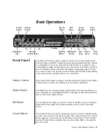
3153 User Manual
Getting Started 1-8
The output amplitude is doubled when the output impedance is above
1 M
Ω
.
High Output -
Channel 2
The channel 2, high output connector outputs fixed (standard)
waveforms to 25 MHz, user (arbitrary) and sequenced waveforms with
sampling clock to 50 MSa/s. Output impedance is 50
Ω
, therefore, for
best performance, the cable connected to this output should be
terminated with 50
Ω
. Output amplitude accuracy is calibrated when
connected to a 50
Ω
load. If the output is connected to a different load
resistance, determine the actual amplitude using the equation above.
High Output -
Channel 3
The channel 3, high output connector outputs fixed (standard)
waveforms to 25 MHz, user (arbitrary) and sequenced waveforms with
sampling clock to 50 MSa/s. Output impedance is 50
Ω
, therefore, for
best performance, the cable connected to this output should be
terminated with 50
Ω
. Output amplitude accuracy is calibrated when
connected to a 50
Ω
load. If the output is connected to a different load
resistance, determine the actual amplitude using the equation above.
Low Output -
Channel 2
The channel 2, low output connector outputs exactly the same
waveforms as the channel 2 high output connector. The only difference
is that the low output has fixed amplitude of 2 Vp-p into 50
Ω. Ε
ither the
high or low output connectors are active. The generator defaults to the
high output connector therefore, a command must be sent to the
instrument to activate the low output connector. The main application for
this output is for I & Q modulation.
Low Output -
Channel 3
The channel 3, low output connector outputs exactly the same
waveforms as the channel 3 high output connector. The only difference
is that the low output has a fixed amplitude of 2 Vp-p into 50
Ω. Ε
ither the
high or low output connectors are active. The generator defaults to the
high output connector therefore, a command must be sent to the
instrument to activate the low output connector. The main application for
this output is for I & Q modulation.
SYNC 1 Output
The SYNC1 output generates a single TTL pulse for synchronizing other
instruments (i.e., an oscilloscope) to the output waveform. The SYNC1
signal always appears at a fixed point relative to the waveform. The
location of the signal along the waveform is programmable.
(
)
V
V
out
prog
=
+
2
50
50
Ω
Ω
R
L
Artisan Technology Group - Quality Instrumentation ... Guaranteed | (888) 88-SOURCE | www.artisantg.com