SD300
POWER ELECTRONICS
190
DESCRIPTION OF PROGRAMMING PARAMETERS
Screen Description
Default
value
Range
Function
Set on
RUN
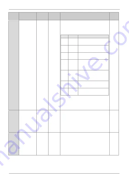
AP.21
Select
feedback
signal source
V1
0 to 6
Select the source through which the
feedback signal will be introduced to close
the control loop.
OPT. DESCR. FUNCTION
0
V1
Feedback
signal
by
voltage analog input 1.
2
V2
Feedback
signal
by
voltage analog input 2.
3
I2
Feedback signal by current
analog input 2.
4
MODB
US
Feedback signal through
Modbus communications
integrated in the drive.
6
COMM
S
Feedback signal through
any
optional
communication boards.
7
PLC
Feedback signal through
the equipment’s PLC.
10
PULSE
Feedback signal through
the pulse input.
Note:
In case an unavailable option is
selected, the parameter will return to its
previous value.
NO
AP.22
PID controller
proportional
gain
+50.00% 0.0 to
1000.0%
Set the value of the proportional gain
controller. This value should be increased
whenever a greater control response is
needed.
Note:
Increasing too much this value can
cause a greater system instability.
YES
AP.23
PID controller
integration
time
10.0ms
0 to
200.0s
Set the regulator integration time. In case
greater precision is needed, increase this
value.
Note:
Increasing this value may slow down
the system.
YES
Summary of Contents for SD 300 Series
Page 1: ...SD300 GETTING STARTED MANUAL LOW VOLTAGE VARIABLE SPEED DRIVE ...
Page 2: ......
Page 3: ...Variable Speed Drive Getting Started Manual Edition February 2019 SD30IM01GI Rev G ...
Page 159: ...POWER ELECTRONICS SD300 DESCRIPTION OF PROGRAMMING PARAMETERS 157 Power off delay ...
Page 174: ...SD300 POWER ELECTRONICS 172 DESCRIPTION OF PROGRAMMING PARAMETERS TI configuration ...
Page 352: ......
Page 353: ......


