PART 1: CX-Programmer
OMRON
CHAPTER 2 – Quick Start Guide
CX-Programmer _Page 23
2. Place a New Contact at the start of the next rung and assign it to symbol ‘RedTimerDone’
(select the symbol name from the combo on the New Contact dialog.
3. Place a New Closed Contact to the right of the Red and Amber Timer and assign it to
symbol ‘GreenTimerDone’.
4. Place a Coil by selecting the
New Coil
button from the toolbar next to the Green Light
Timer. Select ‘RedLight’ from the combo and select the
OK
pushbutton.
5. On the next rung below, place a contact to the left. Assign it to use ‘AmberTimerDone’.
6. To the right of the contact, place a closed contact, and assign it to ‘GreenTimerDone’.
7. To the right of the second contact, place a coil and assign it to ‘RedLight’.
8. On the next rung, place a contact on the left, and assign it to ‘AmberTimerDone’.
9. To the right of the contact, place a closed contact and assign it to ‘GreenTimerDone’.
10. To the right of the second contact, place a coil and assign it to ‘AmberLight’.
11. Press return when the selected cell is on the right of the rung. This will create a new line.
12. Below the left ‘AmberTimerDone’ contact (but on the same rung), place a New Closed
Contact and assign it to the symbol ‘RedTimerDone’.
13. Place a new Vertical by selecting the
New Vertical
button from the toolbar between the
‘GreenTimerDone’ Contact and the ‘AmberLight’ Coil. Connect this to the
‘RedTimerDone’ by placing New Horizontal connections to join to the Vertical by
selecting the
New Horizontal
button from the toolbar.
Note:
Connecting lines can be drawn by clicking the
Line Connect Mode
button
and
then clicking the starting point and dragging to the end point. Connecting lines can also be
deleted by dragging after clicking the
Line Delete Mode
button
. A line can also be drawn
by dragging on a line that is not connected on one end.
14. Place a New Contact at the start of the next rung and assign it to symbol
‘GreenTimerDone’ via the New Contact dialog.
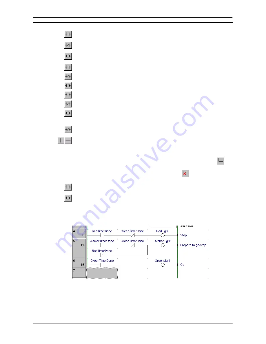
15. Place a Coil next to the contact and assign it to symbol ‘GreenLight’.
The output rungs of the Ladder program should resemble those shown below.
Instructions on the right side of rungs can now also be displayed horizontally (CX-Programmer Ver. 4.0 or
later). Enable this function by selecting
Tools – Options
, and then selecting
Show output instructions
horizontally
in the Diagrams Tab Page
(the default setting is OFF: previously used vertical display). By using
the horizontal display mode, the number of instruction rungs that can be printed and displayed on one screen is
increased, improving the readability of the program. At the same time, the number of printed pages can be
reduced.
Summary of Contents for CX-PROGRAMMER V9
Page 1: ...Cat No W446 E1 12 CX Programmer Ver 9 CXONE AL_C V4 AL_D V4 SYSMAC OPERATION MANUAL...
Page 2: ......
Page 3: ...SYSMAC CX Programmer Ver 9 CXONE AL C V4 AL D V4 Operation Manual Revised July 2010...
Page 4: ......
Page 6: ......
Page 32: ......
Page 33: ...PART 1 CX Programmer...
Page 34: ......
Page 91: ......
Page 111: ......
Page 191: ...PART 1 CX Programmer CHAPTER 4 Reference OMRON CX Programmer _Page 108...
Page 217: ......
Page 233: ......
Page 234: ...PART 2 CX Server PLC Tools...
Page 235: ......
Page 243: ......
Page 249: ......
Page 261: ...PART 2 CX Server PLC Tools CHAPTER 2 PLC Memory Component OMRON CX Server PLC Tools_Page 18...
Page 280: ......
Page 333: ......
Page 377: ......
Page 409: ......
Page 430: ......
Page 431: ...PART 3 CX Server Runtime...
Page 432: ......
Page 476: ......
Page 482: ......
Page 498: ......
Page 524: ......
Page 534: ......
Page 535: ......
Page 536: ......