PART 1: CX-Programmer
CHAPTER 4 – Reference
OMRON
CX-Programmer _Page 78
5. When adding a new symbol, select
Global
to add a symbol to the PLCs symbol table.
Select
Link to the CX-Server file
to share the symbol definition with other applications
(named, global symbols only).
6. Select
the
OK
pushbutton to complete the operation. Select the
Cancel
pushbutton to
abort the operation.
Note:
The
Differentiation
option and
Immediate Refresh
setting can also be set from the contact or
coil context sensitive menu by selecting the element in the Ladder program and clicking the
right-mouse button. A symbol is placed in the Ladder program to indicate that these options
have been set: ‘!’ for Immediate refresh, ‘^’ for Differentiate up; ‘v’ for Differentiate down.
Invert (NOT)
The Invert (NOT) setting allows the normal state of a contact or coil (open or closed) to be reversed. Select
Invert (NOT)
from the context sensitive menu, whilst the contact or coil is selected.
Forced Bits
The state of an address can be ‘forced’ regardless of its physical state. This is useful when testing certain
conditions or rungs in the Ladder program. A bit can be forced on (value changed to 1) or forced off (value
changed to 0), the value of the bit can also be cleared. The following rules apply:
♦
Bit references that are read-only cannot be forced;
♦
Word references may not be forced.
Forcing is only allowed when the PLC is in Debug or Monitor mode (not Run mode).
Use the following procedure to force bits.
1, 2, 3…
1. Obtain the Ladder program and select the element to be forced.
2. Select
Force
from the context sensitive menu, followed by
On
,
Off
or
Cancel
.
Select
Force
from the context sensitive menu, followed by
Cancel All
to cancel all forced bits so that current
values are free to be changed by the PLC program.
Once an element has been forced, a symbol is placed in the Ladder program to indicate that its status has been
forced.
♦
Set
. Set is available from the contact or coil context sensitive menu. The bit can be set to 1 or 0 by selecting
the
Set
option from the contact or coil context sensitive menu followed by
Value
,
To 1
or
To 0
.
♦
Differentiate
.
Differentiate is available from the contact or coil context sensitive menu, performing the
same functions as that within the Edit Contact dialog. Select
Differentiate
from the context sensitive menu,
followed by
Up
or
Down
.
♦
Immediate
.
Immediate Refresh is available from the contact or coil context sensitive menu, performing the
same functions as that within the Edit Contact dialog. Select
Immediate Refresh
from the context sensitive
menu.
♦
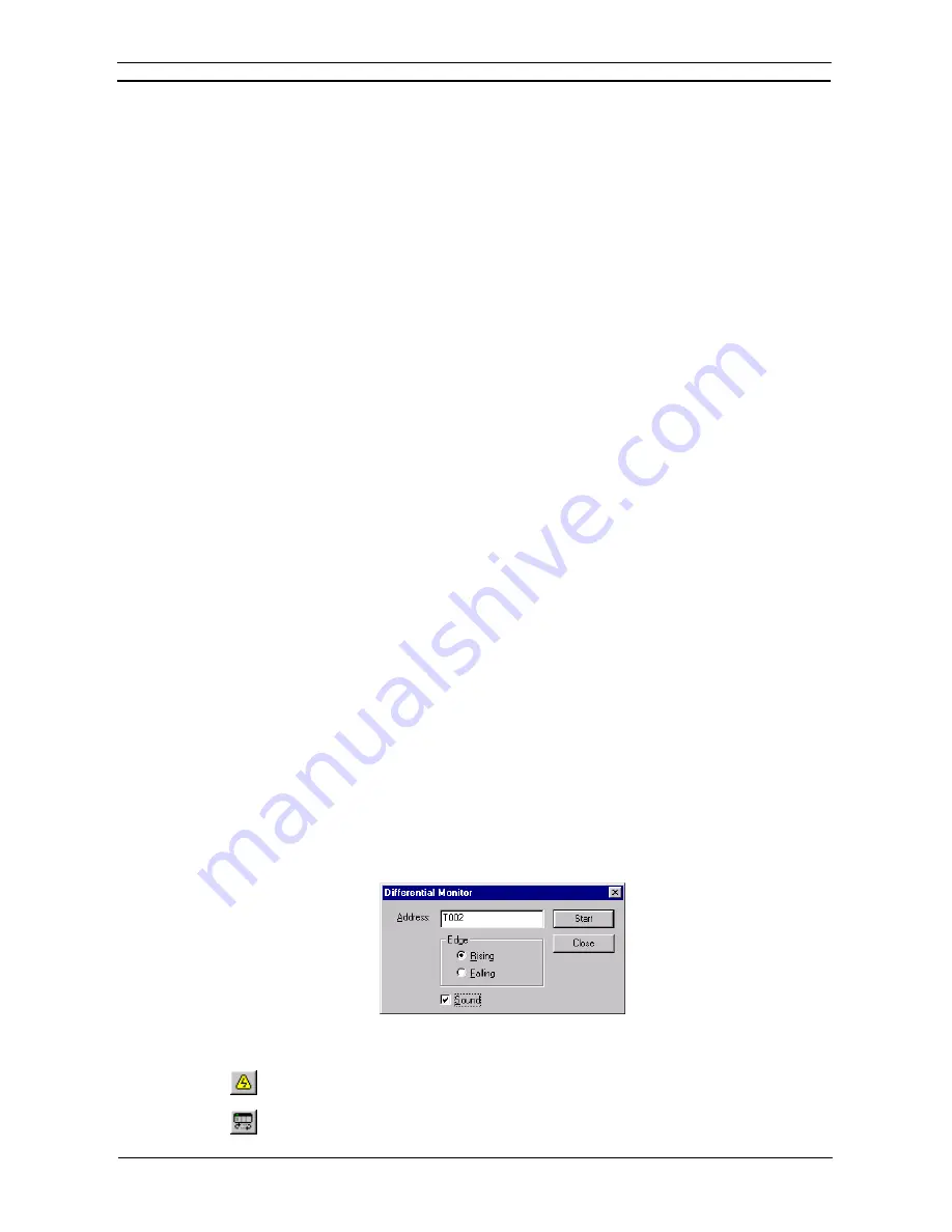
Differential Monitor
.
Differential Monitor is for bits that are not accessible for conventional monitoring
(for instance, values changing too rapidly), but which can be monitored via the Differential Monitor dialog.
The dialog permits the selection of a particular bit to monitor, whether it is monitored against its falling or
rising edge, and whether sound should be used when the bit value changes.
Use the following procedure to apply the differential monitor.
1, 2, 3…
1. Select the Program object in the project workspace to display the Ladder program in the
Diagram Workspace.
2. Select
the
Work On-line
button from the toolbar. A confirmation message is displayed:
select the
Yes
pushbutton to connect to the PLC.
3. Select the
Run Mode
button from the toolbar. Differential monitoring can only be
accomplished in this PLC operating modes and Monitor mode.
Summary of Contents for CX-PROGRAMMER V9
Page 1: ...Cat No W446 E1 12 CX Programmer Ver 9 CXONE AL_C V4 AL_D V4 SYSMAC OPERATION MANUAL...
Page 2: ......
Page 3: ...SYSMAC CX Programmer Ver 9 CXONE AL C V4 AL D V4 Operation Manual Revised July 2010...
Page 4: ......
Page 6: ......
Page 32: ......
Page 33: ...PART 1 CX Programmer...
Page 34: ......
Page 91: ......
Page 111: ......
Page 191: ...PART 1 CX Programmer CHAPTER 4 Reference OMRON CX Programmer _Page 108...
Page 217: ......
Page 233: ......
Page 234: ...PART 2 CX Server PLC Tools...
Page 235: ......
Page 243: ......
Page 249: ......
Page 261: ...PART 2 CX Server PLC Tools CHAPTER 2 PLC Memory Component OMRON CX Server PLC Tools_Page 18...
Page 280: ......
Page 333: ......
Page 377: ......
Page 409: ......
Page 430: ......
Page 431: ...PART 3 CX Server Runtime...
Page 432: ......
Page 476: ......
Page 482: ......
Page 498: ......
Page 524: ......
Page 534: ......
Page 535: ......
Page 536: ......


