PART 3: CX-Server Runtime
OMRON
CHAPTER 2 – Introduction to CX-Server Projects
Revision 2.0
CX-Server Runtime_Page 13
10. Select
the
OK
pushbutton to save the point details or the
Cancel
pushbutton to discard
the new point.
Note:
The fields in the
Address
chapter of the dialog are only enabled when a PLC has been
selected and the values available in these fields (if any) also depend upon the PLC
chosen.
If several points are to be added at a time, the
Leave Box
setting should be checked, this allows the dialog to stay
active after the
Add
pushbutton is pressed. The fields remain populated with the previous point’s settings
allowing further modification. Select the
Close
pushbutton to remove the dialog.
A point can have a name and/or an address. It does not need to have both.
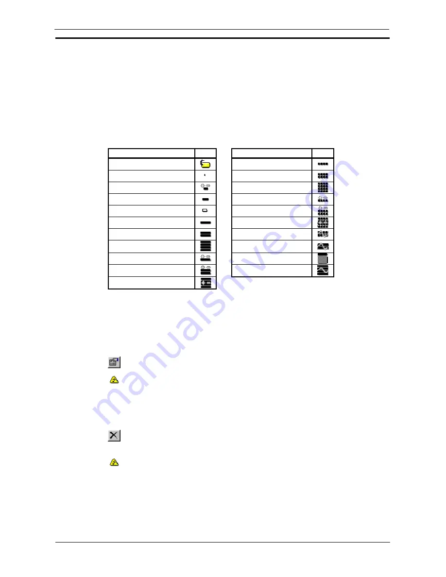
Points with valid addresses assigned are marked by an icon according to the Internal Data Type set as follows:
Internal Data Type
Icon
Internal Data Type
Icon
No type defined
Single Word Unsigned BCD
Bit
Double Word Unsigned BCD
Signed Character Binary
Quad Word Unsigned BCD
Unsigned Character Binary
Single Word Signed BCD
Raw Character Binary
Double Word Signed BCD
Single Word Unsigned Binary
Quad Word Signed BCD
Double Word Unsigned Binary
Double Word Float
Quad Word Unsigned Binary
IEEE Float
Single Word Signed Binary
Complex
Double Word Signed Binary
LReal
Quad Word Signed Binary
Points with an invalid PLC address assigned to them are indicated by the associated icon.
Editing a Point
The Edit Point dialog displays the current configuration for a selected point allowing these details (including the
name) to be amended. The Edit Point dialog operates in the same manner as the Add Point dialog described
above.
1, 2, 3…
1.
Select the point to be edited.
2. Select
the
Properties
button from the toolbar. The Edit Point dialog is displayed. This is
identical to the Add Point dialog.
A point's address or PLC cannot be modified if it is currently active, i.e. open for
communications, indicated by the Device Open icon in the Project Editor.
Deleting a Point or Group
Use the following procedure to delete a point or a group.
1, 2, 3…
1.
Highlight the point or group to be deleted.
2. Select
the
Delete
button from the toolbar to delete the point or group.
A confirmation dialog is displayed provided this option has been set in the Options dialog.
Any points or groups contained within a group being deleted are also removed, unless any
points within the group or children of the group are open for communications, in which case
the points and the groups they are contained within are not deleted.
Points which are currently active cannot be deleted.
Note:
The root group cannot be deleted.
Summary of Contents for CX-PROGRAMMER V9
Page 1: ...Cat No W446 E1 12 CX Programmer Ver 9 CXONE AL_C V4 AL_D V4 SYSMAC OPERATION MANUAL...
Page 2: ......
Page 3: ...SYSMAC CX Programmer Ver 9 CXONE AL C V4 AL D V4 Operation Manual Revised July 2010...
Page 4: ......
Page 6: ......
Page 32: ......
Page 33: ...PART 1 CX Programmer...
Page 34: ......
Page 91: ......
Page 111: ......
Page 191: ...PART 1 CX Programmer CHAPTER 4 Reference OMRON CX Programmer _Page 108...
Page 217: ......
Page 233: ......
Page 234: ...PART 2 CX Server PLC Tools...
Page 235: ......
Page 243: ......
Page 249: ......
Page 261: ...PART 2 CX Server PLC Tools CHAPTER 2 PLC Memory Component OMRON CX Server PLC Tools_Page 18...
Page 280: ......
Page 333: ......
Page 377: ......
Page 409: ......
Page 430: ......
Page 431: ...PART 3 CX Server Runtime...
Page 432: ......
Page 476: ......
Page 482: ......
Page 498: ......
Page 524: ......
Page 534: ......
Page 535: ......
Page 536: ......


